
Concept explainers
(a) Show how you would rewire the protoboard in Figure 5-4(a) so that all the odd-numbered resistors come first followed by the even-numbered ones. (b) Determine the resistance value of each resistor.
FIGURE 5-4
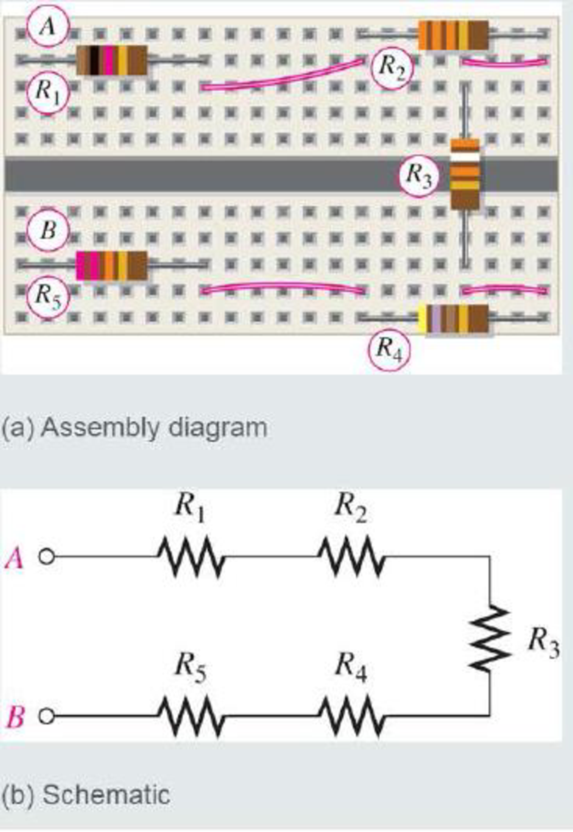
(a)
Show the rewired diagram of the protoboard in given Figure so that all the odd-numbered resistors come first followed by the even-numbered ones.
Explanation of Solution
Discussion:
Refer to given Figure 5-4 in the textbook.
The circuit in given Figure is redrawn as Figure 1 as per the given data.
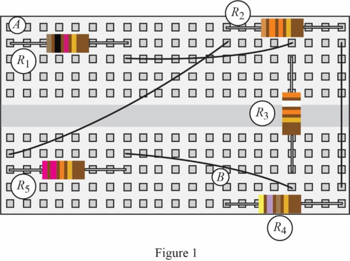
Given that, the odd-numbered resistors are connected first, and then followed by the even-numbered resistors. That is, the resistors
The schematic circuit of Figure 1 is drawn as Figure 2.
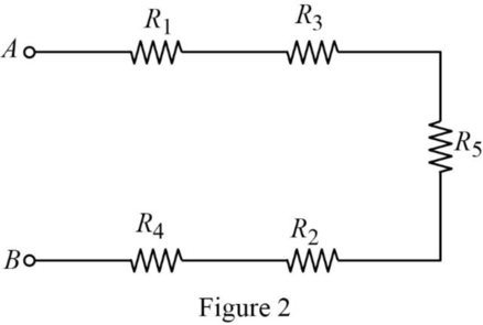
Conclusion:
Thus, the rewired diagram of the given protoboard is drawn.
(b)
Find the resistance value for each of the resistors in the given Figure.
Answer to Problem 1RP
The resistance value for the resistor
Explanation of Solution
Calculation:
Using the standard color codes, the value of the resistors can be calculated. The resistor schematic with 4-band code is drawn as shown in Figure 3.
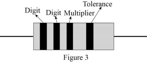
For Resistor
The color code for brown color is digit
Therefore, the value of the resistor
For Resistor
The color code for the first orange color line is digit
Therefore, the value of the resistor
For Resistor
The color code for orange color is digit
Therefore, the value of the resistor
For Resistor
The color code for yellow color is digit
Therefore, the value of the resistor
For Resistor
The color code for the first red color line is digit
Therefore, the value of the resistor
Conclusion:
Thus, the resistance value for the resistor
Want to see more full solutions like this?
Chapter 5 Solutions
Principles Of Electric Circuits
Additional Engineering Textbook Solutions
Fundamentals of Applied Electromagnetics (7th Edition)
Introductory Circuit Analysis (13th Edition)
Electrical Engineering: Principles & Applications (7th Edition)
Thinking Like an Engineer: An Active Learning Approach (4th Edition)
Starting Out with Python (3rd Edition)
C Programming Language


- Determine the resistance values for a voltage divider that must meet the following specifications: The current drawn from the source under unloaded condition is not to exceed 5 mA. The source voltage is to be 10 V, and the required outputs are to be 5 V and 2.5 V. Sketch the circuit.arrow_forwardTwo equal valued resistors dissipate a power of 100W. The resistors are connected in? choices series parallel series-parallelarrow_forwardin the following circuit, an ohmmeter is conntected to points a and b, what is the total resistance of the resistors?arrow_forward
- 1. Two resistors in series are part of a voltage divider circuit with the smaller resistor receiving 30% of the total voltage. () What are the resistance values given that their equivalent resistance is 200 77 {b) If both resistors are rated as 2-W resistors, what is the minimurm total voltage that the voltage divider circuit can handle without exceeding the power rating for either resistor?arrow_forwardAdding more resistors to a parallel circuit will __________ the total resistance. decrease increase not affectarrow_forward10 identical resistors are in parallel. three resistors are connected across a 220v supply. If the total current is 15A, Calculate the value of each resistorarrow_forward
- Kindly help me with c and d, thank you! Two resistors in series rated 4 Ω and 6 Ω are connected in parallel with a 10 Ωresistor. The total parallel combination is connected in series with a 7 Ω resistor and the whole circuit is supplied by a 12-V battery. Determine the following: a.The total resistanceb. The total current c. The current at each of the resistancesd. The voltage across each of the resistancesarrow_forwardDraw a schematic diagram of a parallel circuit connected to 2- 9V batteries (in a series connection) with 3 resistors (3Ω, 4Ω, 6Ω). Find the current and voltage at each resistor and then the overall resistance of the circuit.arrow_forwardA current divider consists of 10 resistors in parallel. Nine of them have equal resistances of 60 kilo-ohms and the tenth is a 20 kilo-ohm resistor. Find the equivalent resistance of the divider, and, if the total current entering the divider is 40mA, find the current in the tenth resistor.arrow_forward
 Delmar's Standard Textbook Of ElectricityElectrical EngineeringISBN:9781337900348Author:Stephen L. HermanPublisher:Cengage Learning
 Electricity for Refrigeration, Heating, and Air C...Mechanical EngineeringISBN:9781337399128Author:Russell E. SmithPublisher:Cengage Learning