
Principles Of Electric Circuits
10th Edition
ISBN: 9780134879482
Author: Floyd, Thomas L.
Publisher: Pearson,
expand_more
expand_more
format_list_bulleted
Concept explainers
Videos
Textbook Question
Chapter 5, Problem 24P
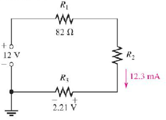
Determine VR1, R2, and R3 in Figure 5-72.
Figure 5-72
Expert Solution & Answer
Want to see the full answer?
Check out a sample textbook solution
Students have asked these similar questions
Determine the current ID for the circuit shown in Figure 5-57 (p. 250). kn = 4.1x10⁻⁴ A/V2, Vtn = 0.75 V.
Figure 5-9 is the graph attached
When two resistors A and B are connected in series, the total resistance is 32ohms. When connected in parallel, the total resistance is 7.5ohms. Determine the possible value of A.
Chapter 5 Solutions
Principles Of Electric Circuits
Ch. 5 - (a) Show how you would rewire the protoboard in...Ch. 5 - How is the circuit changed when pin 2 and pin 3 in...Ch. 5 - Determine the total resistance in Figure 5-10(a)...Ch. 5 - What is the total resistance for the following...Ch. 5 - Determine the value of R4 in Figure 5-12 if the...Ch. 5 - Find RT for three 1.0 k resistors and two 720 ...Ch. 5 - What is the value of R2 if the highest current is...Ch. 5 - Determine V3 if the polarity of VS2 is reversed in...Ch. 5 - Starting with Equation 5-5, prove that the...Ch. 5 - What is the power in the circuit of Figure 5-48 if...
Ch. 5 - Determine the minimum power rating required for...Ch. 5 - Assume that R1 is shorted In Figure 5-61. What...Ch. 5 - A series circuit can have more than one path for...Ch. 5 - The total resistance of a series circuit can be...Ch. 5 - If two series resistors are different sizes, the...Ch. 5 - If two series resistors are different sizes, the...Ch. 5 - If three equal resistors are used in a voltage...Ch. 5 - There is no valid electrical reason for installing...Ch. 5 - Kirchhoffs voltage law is valid only if a loop...Ch. 5 - Prob. 8TFQCh. 5 - Prob. 9TFQCh. 5 - If point A in a circuit has a voltage of +10 V and...Ch. 5 - Two equal-value resistors are connected in series...Ch. 5 - Prob. 2STCh. 5 - Prob. 3STCh. 5 - When one of four series resistors is removed from...Ch. 5 - Prob. 5STCh. 5 - A 9 V battery is connected across a series...Ch. 5 - While putting four 1.5 V batteries in a four-cell...Ch. 5 - If you measure all the voltage drops and the...Ch. 5 - There are six resistors in a given series circuit...Ch. 5 - A series circuit consists of a 4.7 k, a 5.6 k, and...Ch. 5 - Which of the following series combinations...Ch. 5 - The total power in a certain circuit is 1 W. Each...Ch. 5 - When you connect an ammeter in a series-resistive...Ch. 5 - While checking out a series-resistive circuit, you...Ch. 5 - With a 10 V voltage source connected between...Ch. 5 - For the conditions described in Question 1, the...Ch. 5 - When the switches are in position 1 and a short...Ch. 5 - When the switches are in position 2 and a short...Ch. 5 - If the current shown by one of the milliammeters...Ch. 5 - If the source voltage decreases, the current...Ch. 5 - If the current through R1 increases as a result of...Ch. 5 - If the switch is thrown from position A to...Ch. 5 - If the switch is thrown from position B to...Ch. 5 - If the switch is thrown from position C to...Ch. 5 - If R1 is changed to 1.2 k, the voltage from A to B...Ch. 5 - If R2 and R3 are interchanged, the voltage from A...Ch. 5 - If the source voltage increases from 8 V to 10 V,...Ch. 5 - Connect each set of resistors in Figure 563 in...Ch. 5 - Determine the groupings of resistors in Figure 564...Ch. 5 - Determine the nominal resistance between pins 1...Ch. 5 - Determine the nominal resistance between pins 2...Ch. 5 - On the double-sided PC board in Figure 565,...Ch. 5 - Prob. 6PCh. 5 - Prob. 7PCh. 5 - Calculate RT for each circuit of Figure 566....Ch. 5 - What is the total resistance of twelve 5.6 k...Ch. 5 - Six 56 resistors, eight 100 resistors, and two...Ch. 5 - Prob. 11PCh. 5 - You have the following resistor values available...Ch. 5 - Find the total resistance in Figure 566 if all...Ch. 5 - What is the total resistance from A to B for each...Ch. 5 - What is the current through each resistor in a...Ch. 5 - The current from the source in Figure 569 is 5 mA....Ch. 5 - Show how to connect a voltage source and an...Ch. 5 - Using 1.5 V batteries, a switch, and three lamps,...Ch. 5 - What is the current in each circuit of Figure 570?...Ch. 5 - Determine the voltage drop across each resistor in...Ch. 5 - Three 470 resistors are connected in series with...Ch. 5 - Four equal-value resistors are in series with a 5...Ch. 5 - What is the value of each resistor in Figure 571?...Ch. 5 - Determine VR1, R2, and R3 in Figure 5-72. Figure...Ch. 5 - For the circuit in Figure 573 the meter reads 7.84...Ch. 5 - Determine the current measured by the meter in...Ch. 5 - Refer to Figure 5-75. Assume the green LED drops...Ch. 5 - Refer to Figure 5-76. Assume there is a 2.0 V drop...Ch. 5 - Series aiding is a term sometimes used to describe...Ch. 5 - The term series opposing means that sources are in...Ch. 5 - Determine the total source voltage in each circuit...Ch. 5 - Prob. 32PCh. 5 - Five resistors are in series with a 20 V source....Ch. 5 - Determine the unspecified voltage drop(s) in each...Ch. 5 - In the circuit of Figure 5-79, determine the...Ch. 5 - Find R1, R2, and R3 in Figure 580. Figure 580Ch. 5 - Determine the voltage across R5 for each position...Ch. 5 - The total resistance of a circuit is 560 . What...Ch. 5 - Determine the voltage between points A and B in...Ch. 5 - Determine the voltage with respect to ground for...Ch. 5 - Determine the minimum and maximum voltage from the...Ch. 5 - What is the voltage across each resistor in Figure...Ch. 5 - Prob. 44PCh. 5 - If there are 10 V across R1 in Figure 5-86, what...Ch. 5 - Prob. 46PCh. 5 - Prob. 47PCh. 5 - Five series resistors each handle 50 mW. What is...Ch. 5 - If you double the voltage across a resistor, by...Ch. 5 - If the total resistance of a circuit is halved,...Ch. 5 - What is the total power in the circuit in Figure...Ch. 5 - The following W resistors are in series: 1.2 k,...Ch. 5 - Find RT in Figure 587.Ch. 5 - A certain series circuit consists of a W...Ch. 5 - Determine the voltage at each point with respect...Ch. 5 - In Figure 589, how would you determine the voltage...Ch. 5 - Determine the voltage at each point with respect...Ch. 5 - In Figure 589, what is VAC?Ch. 5 - In Figure 589, what is VCA?Ch. 5 - A string of five series resistors is connected...Ch. 5 - By observing the meters in Figure 590, determine...Ch. 5 - What current would you measure in Figure 590(b) if...Ch. 5 - Table 52 shows the results of resistance...Ch. 5 - You measure 15 k between pins 5 and 6 on the PC...Ch. 5 - In checking out the PC board in Figure 591, you...Ch. 5 - The three groups of series resistors on the PC...
Additional Engineering Textbook Solutions
Find more solutions based on key concepts
Explain the main function of each of the following major components of a PLC: a. Processor module (CPU) b. I/O ...
Programmable Logic Controllers
With respect to the circuit in Fig. 5.90, (a) employ Thévenin’s theorem to determine the equivalent network see...
Loose Leaf for Engineering Circuit Analysis Format: Loose-leaf
Three point charges of equal magnitude q, that will yield a zero net electric field at the origin.
Engineering Electromagnetics
When travelers from the USA and Canada visit Europe, they encounter a different power distribution system. Wall...
Electric machinery fundamentals
Write the nodal equations for the network of Fig. 8.137 using the general approach. Find the nodal voltages usi...
Introductory Circuit Analysis (13th Edition)
A constant voltage of 10V is applied to a 50H inductance, as shown in Figure P3.51 Figure P3 51 The current in ...
Electrical Engineering: Principles & Applications (7th Edition)
Knowledge Booster


Learn more about
Need a deep-dive on the concept behind this application? Look no further. Learn more about this topic, electrical-engineering and related others by exploring similar questions and additional content below.Similar questions
- A parallel circuit contains the following resistor values: R1=360R2=470R3=300R4=270lT=0.05A Find the following missing values: RT=l1=Al2=Al3=Al4=Aarrow_forwardFind all missing values for the circuit shown in Figure 6-30 FIGURE 6-30 Determine resistor values using the color code, and determine all missing electrical values.arrow_forwardTwo equal valued resistors dissipate a power of 100W. The resistors are connected in? choices series parallel series-parallelarrow_forward
- Adding more resistors to a parallel circuit will __________ the total resistance. decrease increase not affectarrow_forward100 resistors with value R = 100 Ω are connected in parallel. What is the value of the total resistance?arrow_forwardThe total resistance of five equal resistors connected in parallel is equal toarrow_forward
- Four resistors of 50, 100, 150 and 200 are connected in parallel. Calculate equivalent resistance.arrow_forwardTwo resistors 2.5Ω and 1.2Ω are connected in parallel and take a total current of 60A. Find the current flowing through each resistor.arrow_forwardCircuit Isolution please Two resistors of resistances 5Ω and 7Ω are connected in series across a 60V source. What is the power absorbed in the 5Ω resistor?arrow_forward
- The voltage divider or voltage division technique is normally applied to a circuit or part of the circuit where a _____ source is applied/exist to resistors that are connected in _____. Choose the correct answer: A. voltage, parallel B. current, series C. current, parallel D. voltage, seriesarrow_forwardWhen two resistors are in series, the smaller resistor will have the smaller power dissipation.arrow_forwardResistors R1 and R2 are connected in parallel. The total current drawn from a 30V source is 6A. WHen the value of resistor R2 is doubled, the current drop to 4A. Determine the resistances of R1 and R2arrow_forward
arrow_back_ios
SEE MORE QUESTIONS
arrow_forward_ios
Recommended textbooks for you
 Delmar's Standard Textbook Of ElectricityElectrical EngineeringISBN:9781337900348Author:Stephen L. HermanPublisher:Cengage Learning
Delmar's Standard Textbook Of Electricity
Electrical Engineering
ISBN:9781337900348
Author:Stephen L. Herman
Publisher:Cengage Learning
Current Divider Rule; Author: Neso Academy;https://www.youtube.com/watch?v=hRU1mKWUehY;License: Standard YouTube License, CC-BY