
Concept explainers
Videos
A resistor, R = 4O, and an inductor, L = 1.3 H, are connected in a circuit to a voltage source as shown in Figure (a) (an RL circuit). When the voltage
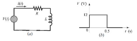
source applies a rectangular voltage pulse with an amplitude of V = 12 V and a duration of 0.5 s, as shown in Figure (b), the current i(t) in the circuit as a
Make a plot of the current as a function of time for
Want to see the full answer?
Check out a sample textbook solution
Chapter 5 Solutions
MATLAB: An Introduction with Applications, 6th Edition: An Introduction with Applications


- An AC circuit contains a 24 resistor, a 15.9-mH inductor, and a 13.3F capacitor connected in parallel. The circuit is connected to a 240-V, 400-Hz power supply. Find the following values. XL=XC=IR=AIL=AIC=AP=WVARsL=VARsC=IT=AVA=PF=%=arrow_forwardDraw the phasor diagram, also write the voltage and current relation statements for the following circuits (i) pure resistor (ii) pure inductor (iii) Resistor and inductor connected in series.arrow_forwardAnswer it clearly Show the complete solution An R-L-C series circuit has a current which lags the applied voltage by 45 degrees. The voltage across the inductance has maximum value equal o twice the maximum value of voltage across the capacitor. Voltage across the inductance is 300 sin (1000t) and R = 20 ohms Find the value of inductance, total impedance and capacitance.arrow_forward
- An inductor and a resistor are in series with a sinewave voltage source. The frequency is set so that the inductive reactance is equal to the resistance. If the frequency is increased, then options: Voltage across the inductor= Source Voltage Voltage across the inductor> Voltage across the resistor Voltage across the inductor= Voltage across the resistor Voltage across the resistor > Voltage across the inductorarrow_forwardAn R-C series circuit has a supply voltage of 100 V. The resistance is 200 ohms and the capacitance is 0.0001 Farad. Solve for the current "i" at any time "t". Solve for the charge "q" at any time "t".arrow_forward6) When the frequency of an a.c. circuit containing resistance and capacitance is decreased, the current (a) decreases (b) increases (c) stays the same 7) In a series a.c. circuit the voltage across a pure inductance is 12 V and the voltage across a pure resistance is 5 V. The supply voltage is (a) 13 V (b) 17 V (c) 7 V (d) 2.4 V 8) The impedance of a coil, which has a resistance of X ohms and an inductance of Y henrys, connected across a supply of frequency K Hz, is (a) 2π Κ Υ (b) X + Y (c) √x² + y² (d) √X² + (2nKY)² 9) When a capacitor is connected to an a.c. supply the current (a) leads the voltage by 180° (c) leads the voltage by 1/2 rad (b) is in phase with the voltage (d) lags the voltage by 90° 10) In an R-L-C series a.c. circuit a current of 5 A flows when the supply voltage is 100 V. The phase angle between current and voltage is 60° lagging. Which of the following statements is false? (a) The circuit is effectively inductive (c) The equivalent circuit reactance is 25 2 (b)…arrow_forward
- 6) When the frequency of an a.c. circuit containing resistance and capacitance is decreased, the current (a) decreases (b) increases (c) stays the same 7) In a series a.c. circuit the voltage across a pure inductance is 12 V and the voltage across a pure resistance is 5 V. The supply voltage is (a) 13 V (b) 17 V (c) 7 V (d) 2.4 V 8) The impedance of a coil, which has a resistance of X ohms and an inductance of Y henrys, connected across a supply of frequency K Hz, is (a) 2π Κ Υ (b) X + Y (c) √x² + y² (d) X² + (2nKY)²arrow_forwardThe current through a 50 mH inductor is given below. Use Ohm’s Law to find the voltage. Convert to polar form, find the impedance and complete the math, then convert back to the waveform at i1 = 7.5sin(2500t – 20°) mA and i2 = 5.9sin(200t + 40°) mAarrow_forwardThe figure below shows a simple RC circuit with a 3.30-μF capacitor, a 4.40-M resistor, a 9.00-V emf, and a switch. What are the following exactly 9.00 s after the switch is closed? (a) the charge on the capacitor 13.7204 UC (b) the current in the resistor 0.0110522 x Your response is off by a multiple of ten. HA (c) the rate at which the capacitor is storing energy μW (d) the rate at which the battery is delivering energy μWarrow_forward
- 6. For the circuit shown in the figure next, the value of (equivalent inductance) L T is found to be * 3. 3. Figure L1 None of the choices O 1.5 04 O 2.5 O3 O O O Oarrow_forwardA series R–L–C circuit comprises a 5µF capacitor, a 4ohm resistor and a variable inductance L. The supply voltage is 10∠0◦ V at a frequency of 159.1 Hz. The inductance is adjusted until the p.d. across the 4 ohm resistanceis a maximum. Determine for this condition (a) the value of inductance, (b) the p.d. across each component and (c) the Q-factor of the circuit.arrow_forward(b) Find the equivalent inductance of the circuit in Figure Q3(b). 8mH 6mH a 5mH 12mH 8mH ) 4mH 6mH 10mH 8mH Figure Q3(b)arrow_forward
 Delmar's Standard Textbook Of ElectricityElectrical EngineeringISBN:9781337900348Author:Stephen L. HermanPublisher:Cengage Learning