
Concept explainers
Videos
Determine the Norton equivalent of the circuit depicted in Fig. 5.74 as seen looking into the two open terminals. (b) Compute power dissipated in a 5 Ω resistor connected in parallel with the existing 5 Ω resistor. (c) Compute the current flowing through a short circuit connecting the two terminals.
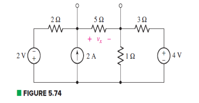
(a)
Find the Norton equivalent of the circuit as seen looking into the two open terminals.
Answer to Problem 33E
The Norton current is
Explanation of Solution
Formula used:
The expression for voltage is as follows.
Here,
The expression for series combination of resistance is as follows.
Here,
The expression for parallel combination of resistance is as follows.
Here,
Calculation:
The circuit diagram is redrawn as shown in Figure 1.
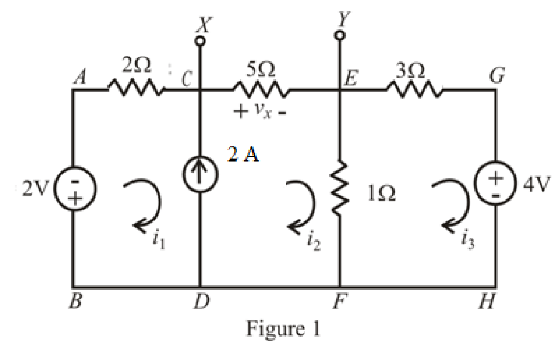
Refer to redrawn Figure 1,
The expression for KVL in super mesh
Here,
Substitute
The expression for KVL in mesh
Here,
Substitute
The expression for current
Here,
Substitute
Rearrange equations(5),(7) and (9).
The equations so formed can be written in matrix form as,
Therefore, by Cramer’s rule,
The determinant of coefficient matrix is as follows.
The 1st determinant is as follows.
The 2nd determinant is as follows,
The 3rd determinant is as follows.
Simplify for
Simplify for
Simplify for
Substitute
So, the Thevenin voltage is
The circuit diagram is redrawn as shown in Figure 2.
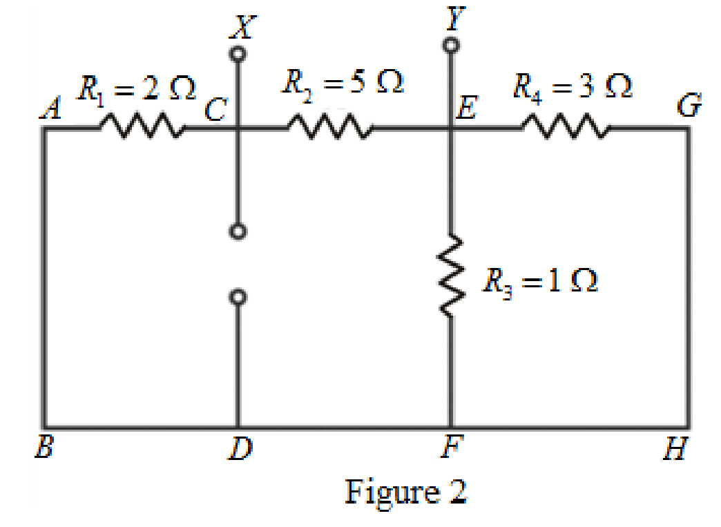
As
Rearrange for
The circuit diagram is redrawn as shown in Figure 3.
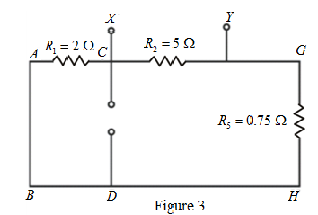
As
The circuit diagram is redrawn as shown in Figure 4.
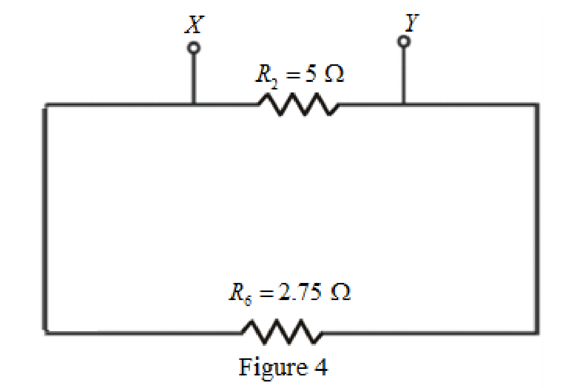
Refer to redrawn Figure 4,
As
Rearrange for
So, the Thevenin equivalent resistance across the branch
Thevenin equivalent resistance is same as the Norton equivalent resistance,
Hence,
The circuit diagram is redrawn as shown in Figure 5,
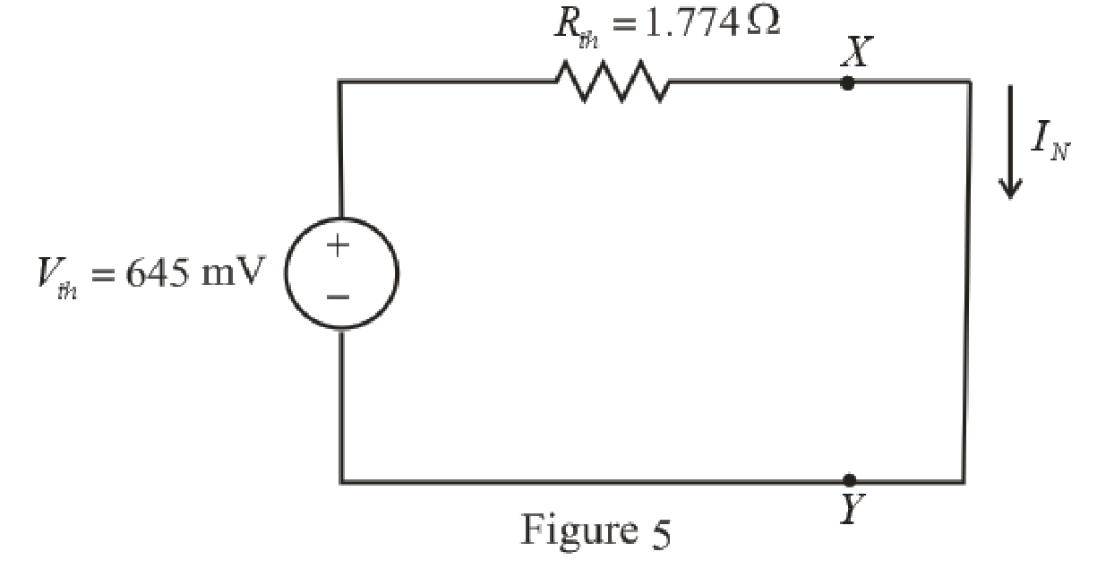
Refer to redrawn Figure 5,
Norton current is the current in the load resistor when load resistance is replaced by a short circuit.
The expression for the Norton current flowing in the circuit is as follows,
Here,
Substitute
Conclusion:
Thus the Norton current is
(b)
Find the power dissipated in a
Answer to Problem 33E
The power dissipated in a
Explanation of Solution
Given Data:
The load resistance is
Formula used:
The expression for the power dissipated in a resistor is as follows,
Here,
Calculation:
The circuit is drawn as shown in Figure 6,
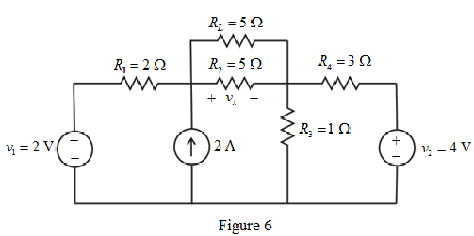
Refer to redrawn Figure 6,
The simplified Norton equivalent of the circuit is drawn as shown in Figure 7,
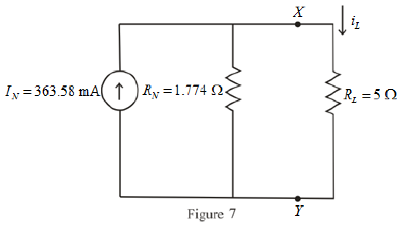
Refer to redrawn Figure 7,
The expression for the current flowing through the load is as follows,
Substitute
Substitute
Conclusion:
Thus, the power dissipated in a
(c)
Find the current flowing through a short circuit connecting the two terminals.
Answer to Problem 33E
The current flowing through a short circuit connecting the two terminals is
Explanation of Solution
Calculation:
The current flowing through a short circuit connecting the two terminals is Norton current which is
So, the current flowing through a short circuit connecting the two terminals is
Conclusion:
Thus, the current flowing through a short circuit connecting the two terminals is
Want to see more full solutions like this?
Chapter 5 Solutions
Loose Leaf for Engineering Circuit Analysis Format: Loose-leaf


- Kindly provide CLEAR and COMPLETE solutions #5arrow_forwardFor each configuration in Fig. 5.85, find the individual (not combinations of) elements (voltages sources and/or resistors) that are in series. If necessary, use the fact that elements in series have the same current. Simply list those that satisfy the conditions for a series relationship.arrow_forwardCalculate the voltage ratio vo/vs for the op amp circuit of Fig. 5.51. Assume that the op amp is ideal.arrow_forward
- Calculate input impedance Zwe of circuit with ideal transformed (Fig. 5.19). Assume: R=1Ω, XL=1Ω, XC=2Ω.arrow_forward7 Renewable Energy Sources are readily available everywhere, whole year round. Select one: True Falsearrow_forwardIf in the circuit of Example 5.5 the value of R, is doubled (to 13.1 k52), find approximate values for I, and V» Ans. 0.15 mA: 0.05 V Need workarrow_forward
- engineering economics Valley Rendering, Inc. is considering purchasing a new flotation system for grease recovery. The company can finance a $150,000 system at 5% per year compound interest or 5.5% per year simple interest. If the total amount owed is due in a single payment at the end of 3 years, (a) which interest rate should the company select, and (b) how much is the difference in interest between the two schemes?arrow_forwardProvide an overview of "Two Externally-powered transducers".Support your answer with pictures and examplesarrow_forwardThe system of using helicopters to work on live power lines is based on the principle that electrical current seeks to flow into the ground. Select one: True Falsearrow_forward
- 1. A thyristor operating from a peak supply voltage of 400 V has the followingspecifications:Repetitive peak current, Ip = 200 A, = 50 A/µs, = 200 V/ µs. Choosing a factor safety forthe above-mentioned parameters, design a suitable snubber circuit. The minimum valueof load resistance is 10 Ω. 2. A boost converter with vin = 12 V is required to be designed for a 100 W rating. If theoutput voltage is maintained at 96 V, find out load resistance and duty ratio. Furtherdesign the filter components in consideration with a ripple of 10% and 5% in inputcurrent and output voltage. Take the switching frequency be 30 kHz. 3. Following are the specifications of a thyristor operating from a peak voltage supply of500 V: Repetitive peak current, Ip = 250 A, = 60 A/µs, = 200 V/µs. Take the factor ofsafety of 2 for the three specifications mentioned above. Design a suitable snubber circuitif the minimum load resistance is 20 Ω. Take ξ = 0.65. 4. A buck–boost converter operating at 20 kHz, L = 0.05 mH.…arrow_forward4a- Please solve this question in detail. Thanksarrow_forward5b. Is the system stable? Justify your answer.arrow_forward
 Introductory Circuit Analysis (13th Edition)Electrical EngineeringISBN:9780133923605Author:Robert L. BoylestadPublisher:PEARSON
 Delmar's Standard Textbook Of ElectricityElectrical EngineeringISBN:9781337900348Author:Stephen L. HermanPublisher:Cengage Learning
 Programmable Logic ControllersElectrical EngineeringISBN:9780073373843Author:Frank D. PetruzellaPublisher:McGraw-Hill Education
 Fundamentals of Electric CircuitsElectrical EngineeringISBN:9780078028229Author:Charles K Alexander, Matthew SadikuPublisher:McGraw-Hill Education
 Electric Circuits. (11th Edition)Electrical EngineeringISBN:9780134746968Author:James W. Nilsson, Susan RiedelPublisher:PEARSON
 Engineering ElectromagneticsElectrical EngineeringISBN:9780078028151Author:Hayt, William H. (william Hart), Jr, BUCK, John A.Publisher:Mcgraw-hill Education,