
Concept explainers
The factor of safety for yielding from distortion-energy theory.
The factor of safety for yielding from maximum-shear-stress theory.
Answer to Problem 42P
The factor of safety for yielding from distortion-energy theory is
The factor of safety for yielding from maximum-shear-stress theory is
Explanation of Solution
The given assumption is that the belt tension on the loose side at
Write the relationship between tension on the loose side with respect to tension on the tight side.
Here, the tension on the tight side is
Write the equation to balance the tension on the counter shaft.
Substitute
Calculate the tension on the loose side.
Here, the tension on the tight side of pulley
Write the magnitude of bearing reaction force at
Here, the tension on tight side of pulley
Write the magnitude of bearing reaction force at
Write the magnitude of bearing reaction force at
Here, the magnitude of bearing force at
Write the magnitude of bearing force at
Here, the magnitude of bearing reaction force at
Calculate the bearing reaction force at
Here, the bearing reaction force at
Calculate the bearing reaction force at
Here, the bearing reaction force at
The calculations for shear force and bending moment diagram in
Calculate the shear force at
Here, the shear force at
Calculate the shear force at
Here, the shear force at
Calculate the shear force at
Here, the shear force at
Calculate the moment at
The moment at the supports of the simply supported beam is zero.
Calculate the moment at
Here, the moment at
The calculations for shear force and bending moment diagram in
Calculate the shear force at
Here, the shear force at
Calculate the shear force at
Here, the shear force at
Calculate the shear force at
Calculate the shear force at
Here, the shear force at
Calculate the moment at
The moment at the supports of the simply supported beam is zero.
Calculate the moment at
Here, the moment at
Calculate the moment at
Here, the moment at
It is clear from the bending moment diagrams, that the critical location is at
Write the net moment at
Here, the net moment at
Write the torque transmitted by shaft from
Here, the torque transmitted by shaft from
Calculate the bending stress.
Here, the bending stress is
Calculate the shear stress.
Here, the shear stress is
Calculate the maximum principal stress.
Here, the maximum principal stress is
Calculate the minimum principal stress.
Here, the minimum principal stress is
Calculate the maximum shear stress.
Here, maximum shear stress is
Calculate the factor of safety from maximum-shear-stress theory.
Here, the maximum yield stress for
Calculate the factor of safety from distortion-energy theory.
Here, the Von Mises stress is
Write the expression for von Mises stress.
Substitute
Conclusion:
Substitute
Substitute
Substitute
Substitute
Substitute
Substitute
Substitute
Substitute
Substitute
Substitute
Substitute
Substitute
Thus, the shear force diagram and bending moment diagram for the shaft in
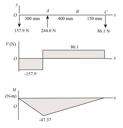
Figure (1)
Substitute
Substitute
Substitute
Substitute
Substitute
Substitute
Thus, the shear force diagram and bending moment diagram for the shaft in
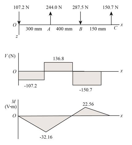
Figure (2)
Substitute
Substitute
Convert diameter of shaft into
Substitute
Substitute
Substitute
Substitute
Substitute
Refer to the Table A-20 “Deterministic ASTM Minimum Tensile and Yield Strengths for Some Hot-Rolled (HR) and Cold-Drawn (CD) Steels” and obtain
Substitute
Thus, the factor of safety for yielding from maximum-shear-stress theory is
Substitute
Thus, the factor of safety for yielding from distortion-energy theory is
Want to see more full solutions like this?
Chapter 5 Solutions
SHIGLEY'S MECH.ENGINEERING DESIGN-EBK>I


- B).shear stress caused by T C).APply miaximum-Distortion-energy Theory and calculate Mises equivalent stress. Enter your answer in MPa to 2 decimal places. D). determine factor of safety n (upto 2 decimal places)arrow_forwardBar of steel, (yield strenght Sy = 462 MPa) is subjected to the following stresses; σx = 171 MPa , σy = -144 MPa , τxy = 175 MPa Using the Distortion-Energy Theory determine the factor of safety and check is the bar will fail or not.arrow_forwardA material is subjected to plane stress. Express the distortion energy theory of failure in terms of sx, sy, and txy.arrow_forward
- The stresses on the surface of a hard bronze component are shown in the figure below. The yield strength of the bronze is σY = 345 MPa.a) What is the factor of safety predicted by the maximum-shear-stress theory of failure for the stress state shown? Does the component fail according to this theory?b) What is the value of the Mises equivalent stress for the given state of plane stress?c) What is the factor of safety predicted by the failure criterion of the maximum-distortion energy theory of failure? Does the component fail according to this theory?arrow_forwardin the design of shafts made of ductile materials subjected to twisting moment and bending moment, the recommended theory of failure is (a) maximum principal stress theory (b) maximum principal strain theory (c) maximum shear stress theory (4) maximum strain-energy theoryarrow_forwardA Steel shaft is subjected to an end thrust producing a stress of 90 MPa and the minimum shearing stress on the surface arising from torsion is 60 MPa .The yield point stress of the material in simple tension was found to be 300 MPa. calculate the factor of safety of the shaft according to the following theory 1)maximum shear stress theoryarrow_forward
- A shaft is loaded by a torque of 5 KN-m. The material has a yield point of350 MPa. Find the required diameter using(a) Maximum shear stress theory(b) Maximum distortion energy theoryTake a factor of safety of 2.5.arrow_forwardDetermine the yield strength of a material required such that the component would not fail when subject to the following stresses sigma1 = 2 MPa and sigma 2= -15 MPa sigma 3 = 10 MPa). Use a yield criterion that assumes that yield failure will occur when the maximum shear stress in the complex system becomes equal to the limiting shear strength in a simple tensile test.arrow_forwardThe armature shaft of a 50 kW, 580 rpm electric motor, mounted on two bearings A and B, is shown in Fig. The total magnetic pull on the armature is 5 kN and it can be assumed to be uniformly distributed over a length of 400 mm midway between the bearings. The shaft is made of steel with an ultimate tensile strength of 770 N/mm2 and yield strength of 580 N/mm2. Determine the shaft diameter using the ASME code if, kb=1.5 and kt=1.0 Assume that the pulley is keyed to the shaft.arrow_forward
- A motor driving a solid circular steel shaft with diameter d = 1.5 in, transmits 50 hp to a gear at B, The allowable shear stress in the steel is 6000 psi. Calculate the required speed of rotation (number of revolutions per minute) so that the shear stress in the shaft does not exceed the allowable limit.arrow_forwardTorque in = 40nm Holding torque out = 896nm 8.Using your answers from the gear box above, and given that the input shaft has a diameter of 12 mm and the output shaft has a diameter of 15 mm, both shafts are made from aluminium. When this transmission system was operated, it failed. Identify the position where the failure occurred and the reason for this failure. Suggests improvements to the system to overcome the failure mode. The shear strength of aluminium is 207 MPa.arrow_forwardWhat length of a square key is required for a 5-in diameter shaft transmitting 1000 hp at 1000 rpm? The allowable shear and compressive stresses in the key are 15 ksi and 30 ksi, respectively.arrow_forward
 Mechanics of Materials (MindTap Course List)Mechanical EngineeringISBN:9781337093347Author:Barry J. Goodno, James M. GerePublisher:Cengage Learning