
Concept explainers
The factor of safety for yielding from distortion-energy theory.
The factor of safety for yielding from maximum-shear-stress theory.
Answer to Problem 45P
The factor of safety for yielding from distortion-energy theory is
The factor of safety for yielding from maximum-shear-stress theory is
Explanation of Solution
The figure below shows the arrangement of shafts.
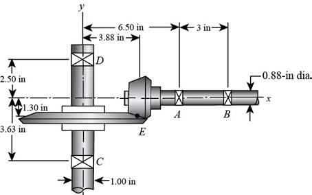
Figure (1)
The free body diagram of the arrangement of shafts is as follows.
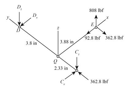
Figure (2)
Write the expression of moment at
Here, the reaction at
Write the expression of moment at
Here, the reaction at
Write the expression of moment at
Here, the reaction at
Write the expression of moment at
Write the expression of net force at
Here, the reaction at
It is clear from the free body diagram of the shaft
The calculations for shear force diagram in
Write the expression of Shear force at
Here, the shear at
Write the expression of Shear force at
Here, the shear force at
Write the expression of Shear force at
Here, the shear force at
The calculations for bending moment diagram in
We known that, the bending moment at the supports of the simply supported beam is zero.
Write the bending moment at
Here, the bending moment at
Write the expression of bending moment at
Here, the bending moment at
Write the expression of bending moment at
Here, the bending moment at
The calculations for shear force diagram in
Write the expression of Shear force at
Here, the shear at
Write the expression of Shear force at
Here, the shear force at
Write the expression of Shear force at
Here, the shear force at
The bending moment at the supports of the simply supported beam is zero.
Write the bending moment at
Here, the bending moment at
Write the expression of bending moment at
Here, the bending moment at
It is clear from the bending moment diagram that the critical stress element is located at just right of
Write the expression of maximum torque acting on the shaft
Here, the maximum torque acting on the shaft
Write the expression of maximum bending moment acting on the shaft
Here, the maximum bending moment acting on the shaft
Write the expression of torsional shear stress for critical stress element.
Here, the torsional shear stress for critical stress element is
Write the expression of bending stress for critical stress element.
Here, the bending stress for critical stress element is
Write the expression of axial stress for critical stress element.
Here, the axial stress for critical stress element is
Write the expression of maximum bending stress on the critical stress element.
Here, the maximum bending stress on the critical stress element is
Write the expression of principal stresses on the critical stress element.
Here, the principal stresses on the critical stress element are
Write the expression of maximum shear stress on the critical stress element.
Here, the maximum shear stress on the critical stress element is
Calculate the factor of safety from maximum-shear-stress theory.
Here, the maximum yield stress for
Calculate the factor of safety from distortion-energy theory.
Here, the Von Mises stress is
Write the expression for von Mises stress.
Substitute
Conclusion:
Substitute
Thus, the reaction at
Substitute
Thus, the reaction at
Substitute
Thus, the reaction at
Substitute
Thus, the reaction at
Substitute
Thus, the reaction at
Substitute
Substitute
Substitute
Substitute
Substitute
The figure below shows the shear force and bending moment diagram in
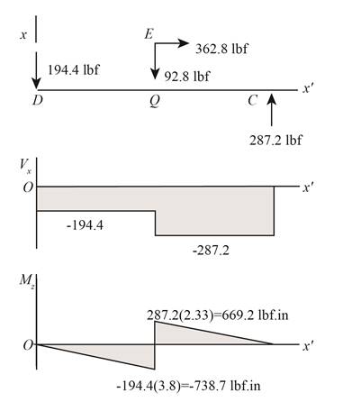
Figure (3)
Substitute
Substitute
Substitute
Substitute
The figure below shows the shear force and bending moment diagram in
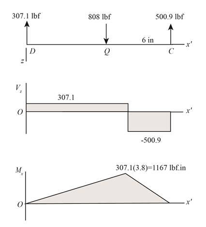
Figure (4)
Substitute
Substitute
Substitute
Thus, the torsional shear stress for critical stress element is
Substitute
Thus, the bending stress for critical stress element is
Substitute
Thus, the axial stress for critical stress element is
Substitute
Substitute
Substitute
Refer to the Table A-20 “Deterministic ASTM Minimum Tensile and Yield Strengths for Some Hot-Rolled (HR) and Cold-Drawn (CD) Steels” and obtain the yield strength as
Substitute
Thus, the factor of safety for yielding from maximum-shear-stress theory is
Substitute
Thus, the factor of safety for yielding from distortion-energy theory is
Want to see more full solutions like this?
Chapter 5 Solutions
Shigley's Mechanical Engineering Design (McGraw-Hill Series in Mechanical Engineering)


- Two sections of steel drill pipe, joined by bolted flange plates at Ä are being tested to assess the adequacy of both the pipes. In the test, the pipe structure is fixed at A, a concentrated torque of 500 kN - m is applied at x = 0.5 m, and uniformly distributed torque intensity t1= 250 kN m/m is applied on pipe BC. Both pipes have the same inner diameter = 200 mm. Pipe AB has thickness tAB=15 mm, while pipe BC has thickness TBC= 12 mm. Find the maximum shear stress and maximum twist of the pipe and their locations along the pipe. Assume G = 75 GPa.arrow_forwardThe stepped shaft shown in the figure is required to transmit 600 kW of power at 400 rpm. The shaft has a full quarter-circular fillet, and the smaller diameter D1= 100 mm. If the allowable shear stress at the stress concentration is 100 MPa, at what diameter will this stress be reached? Is this diameter an upper or a lower limit on the value of D2?arrow_forwardA propeller shaft for a small yacht is made of a solid steel bar 104 mm in diameter. The allowable stress in shear is 48 MPa, and the allowable rate of twist is 2.0° in 3.5 meters. (a) Assuming that the shear modulus of elasticity is G = 80 GPa, determine the maximum torque that can be applied to the shaft. (b) Repeat part (a) if the shaft is now hollow with an inner diameter of 5d18. Compare values to corresponding values from part (a).arrow_forward
- A solid brass bar of diameter d = 1.25 in. is subjected to torques T1as shown in part a of the figure. The allowable shear stress in the brass is 12 ksi. What is the maximum permissible value of the torques T1? If a hole of diameter 0.625 in. is drilled longitudinally through the bar, as shown in part b of the figure, what is the maximum permissible value of the torques T2? What is the percent decrease in torque and the percent decrease in weight due to the hole?arrow_forwardA motor driving a solid circular steel shaft with diameter d = 1.5 in, transmits 50 hp to a gear at B, The allowable shear stress in the steel is 6000 psi. Calculate the required speed of rotation (number of revolutions per minute) so that the shear stress in the shaft does not exceed the allowable limit.arrow_forwardA hollow tube ABCDE constructed of monel metal is subjected to five torques acting in the directions shown in the figure. The magnitudes of the torques are T1= 1000 lb-in., T2= T4= 500 lb-in., and T3= T5= 800 lb-in. The tube has an outside diameter of d2= 1.0 in. The allowable shear stress is 12,000 psi and the allowable rate of twist is 2.0°/ft. Determine the maximum permissible inside diameter d1, of the tube.arrow_forward
- A stepped shaft ABC consisting of two solid, circular segments is subjected to torques T}and T2acting in opposite directions, as shown in the figure. The larger segment of the shaft has a diameter of dv- 2.25 in. and a length Lt= 30 in.; the smaller segment has a diameter d2— 1.75 in. and a length L, = 20 in. The torques are T, = 21,000 lb-in. and fz=10.000 lb-in. (a) Find reaction torque TAat support A. (b) Find the internal torque T(x) at two locations: x = L1/2 and x = L1+ L2/2. Show these internal torques on properly drawn free-body diagrams (FBDs).arrow_forwardThe composite shaft shown in the figure is manufactured by shrink-Fitting a steel sleeve over a brass core so that the two parts act as a single solid bar in torsion. The outer diameters of the two parts are dY= 40 mm for the brass core and d2= 50 mm for the steel sleeve. The shear moduli of elasticity are Gb= 36 GPa for the brass and Gs= 80 GPa for the steel. (a) Assuming that the allowable shear stresses in the brass and steel are rb= 48 MPa and ts= 80 MPa, respectively, determine the maximum permissible torque Tmax that may be applied to the shaft. (b) If the applied torque T = 2500 kN · m, find the required diameter d2so that allowable shear stress t3is reached in the steel.arrow_forwardSolve the preceding problem for the following data:P = 160 kN,JV = 200 tN,L = 2 m,b = 95 mm, h = 300 mm, and d = 200 mmarrow_forward
- Solve the preceding problem if the shaft has an outer diameter d2=150 mm and inner diameter d1= 100 mm. Also, the steel has a shear modulus of elasticity G = 75 GPa, and the applied torque is 16 kN ·m.arrow_forwardA circular steel tube with an outer diameter of 75 mm and inner diameter of 65 mm is subjected to torques 7"at its ends. Calculate the maximum permissible torque 7jliajl if the allowable normal strain is ea= 5 X 10"4 Assume that G = 15 GPa.arrow_forwardA solid aluminum bar (G = 27 GPa ) of diameter d = 40 mm is subjected to torques T = 300 N - m acting in the directions shown in the figure, Determine the maximum shear, tensile, and compressive stresses in the bar and show these stresses on sketches of properly oriented stress elements. Determine the corresponding maximum strains (shear, tensile, and compressive) in the bar and show these strains on sketches of the deformed elements.arrow_forward
 Mechanics of Materials (MindTap Course List)Mechanical EngineeringISBN:9781337093347Author:Barry J. Goodno, James M. GerePublisher:Cengage Learning