Videos
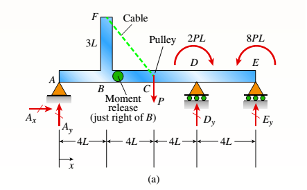
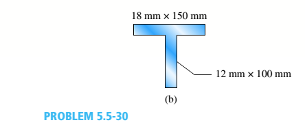
Beam ABCDE has a moment release just right of joint B and has concentrated moment loads at D and E. In addition, a cable with tension P is attached at fand runs over a pulley at C (Fig, a). The beam is constructed using two steel plates, which arc welded to form a T cross section (see Fig. b). Consider ßexuralstresses only Find the maximum permissible value of load variable P if the allowable bending stress is 130 M Pa. Ignore the self-weight of the frame members and let length variable L = 0.75 m.
The maximum permissible load.
Answer to Problem 5.5.30P
The maximum permissible load is
Explanation of Solution
Given information:
The allowable bending stress is
Write the expression for the force equilibrium in x direction.
Here, the reaction at point
Write the expression for the moment at the point of release.
Here, the length of the beam is
Write the expression for the moment about point
Here, the vertical reaction at point
Write the expression for the force equilibrium in y direction.
Here, the vertical reaction at point
Write the expression for the moment at
Here the moment is
Write the expression for the moment at
Write the expression for the moment at
Write the expression for the moment at other points.
Write the expression for the area of the
Here, the width of the flange is
Write the expression for the centroid.
Here, the distance of the centroid from one end is
Write the expression for the other distance of the centroid.
Here, the distance of the centroid from other end is
Write the expression for the moment of inertia about z axis.
Here, the moment of inertia about z axis is
Write the expression for the section modulus at the top section.
Here, the section modulus at top section is
Here, the section modulus of top section is
Write the expression for the section modulus at the bottom section.
Here, the section modulus of bottom section is
Write the expression for the maximum permissible load.
Here, the allowable stress is
Calculation:
Substitute
Substitute
Substitute
Substitute
Substitute
Substitute
Substitute
Substitute
Substitute
Conclusion:
The maximum permissible load is
Want to see more full solutions like this?
Chapter 5 Solutions
Mechanics of Materials - MindTap Access


- A wood beam 8 in. wide and 12 in. deep (nominal dimensions) is reinforced on top and bottom by 0,25-in.-thick steel plates (see figure part a), (a) Find the allowable bending moment A/max about the z axis if the allowable stress in the wood is 1100 psi and in the steel is 15,000 psi, (Assume that the ratio of the moduli of elasticity of steel and wood is 20.) (b) Compare the moment capacity of the beam in part a with that shown in the figure part b which has two 4 in. × 12 in, joists (nominal dimensions) attached to a 1/4 in, × 11.0 in, steel plate.arrow_forwardA cantilever beam AB of length L = 6.5 ft supports a trapezoidal distributed load of peak intensity 4, and minimum intensity q/2tthat includes the weight of the beam (see figure). The beam is a steel W 12 × 14 wide-flange shape (see Table F-l(a), Appendix F). Calculate the maximum permissible load q based upon (a) an allowable bending stress eallow = 18 ksi and (b) an allowable shear stress eallow = 7,5 ksi. Note: Obtain the moment of inertia and section modulus of the beam from Table F-l(a).arrow_forwardA r o lukI f/frm f «m t ub e of ou t sid e d ia met er ^ and a copper core of diameter dxare bonded to form a composite beam, as shown in the figure, (a) Derive formulas for the allowable bending moment M that can be carried by the beam based upon an allowable stress <7Ti in the titanium and an allowable stress (u in the copper (Assume that the moduli of elasticity for the titanium and copper are Er- and £Cu, respectively.) (b) If d1= 40 mm, d{= 36 mm, ETl= 120 GPa, ECu= 110 GPa, o-Ti = 840 MPa, and ctqj = 700 MPa, what is the maximum bending moment Ml (c) What new value of copper diameter dtwill result in a balanced design? (i.e., a balanced design is that in which titanium and copper reach allow- able stress values at the same time).arrow_forward
- A simple beam of length L = 5 m carries a uniform load of intensity q = 5,8 kN/m and a concentrated load 22.5 kN (see figure). (a) Assuming tra]]ow = 110 MPa, calculate the required section modulus S. Then select the most economical wide-flange beam (W shape) from Table F-l(b) in Appendix F, and recalculate S, taking into account the weight of the beam. Select a new beam if necessary. (b) Repeat part (a), but now assume that the design requires that the W shape must be used in weak axis bending (i.e., it must bend about the 2-2 (or y) axis of the cross section).arrow_forwardA steel beam ABC is simply supported at A and fiand has an overhang BC of length L = 150 mm (see figure). The beam supports a uniform load of intensity q = 4,0 kN/m over its entire span AB and l.5g over BC. The cross section of the beam is rectangular with width h and height 2b. The allowable bending stress in the steel iso"a|]ûW = 60 MPa, and its weight density is y = 77.0 kN/m . Disregarding the weight of the beam, calculate the required width b of the rectangular cross section. Taking into account the weight of the beam, calculate the required width b.arrow_forwardThe hollow box beam shown in the figure is subjected to a bending moment M of such magnitude that the flanges yield but the webs remain linearly elastic. (a) Calculate the magnitude of the moment M if the dimensions of the cross section are A = 15 in., A] = 12.75 in., h = 9 in., and ey =7.5 in. Also, the yield stress is eY = 33 ksi. (b) What percent of the moment M is produced by the elastic core?arrow_forward
- A reinforced concrete T-beam (see figure) is acted on by a positive bending moment of M = 175 kip-ft. Steel reinforcement consists of four bars of 1.41-inch diameter. The modulus of elasticity for the concrete is Ec= 3000 ksi while that of the steel is £s = 29,000 ksi. Let b = 48 im, rf = 4 in., bw=15 in,, and d = 24 in, Find the maximum stresses in steel and concrete, If allowable stresses for concrete and steel are o"ac = 1400 psi and tr^ =18 ksi, respectively, what is the maximum permissible positive bending moment?arrow_forwardA composite beam consisting of fiberglass faces and a core of particle board has the cross section shown in the figure. The width of the beam is 2,0 in., the thickness of the faces is 0,10 in., and the thickness of the core is 0.50 in. The beam is subjected to a bending moment of 250 lb-in, acting about the - axis. Find the maximum bending stresses tr(and ctc in the faces and the core, respectively, if their respective moduli of elasticity are 4 x 10⁶ psi and 1.5 x 10⁶ psi.arrow_forwardA propped cantilever beam of length L = 54 in. with a sliding support supports a uniform load of intensity q (see figure). The beam is made of steel {<7y = 36 ksi) and has a rectangular cross section of width/) = 4.5 in. and height h = 6.0 in. What load intensity q will produce a fully plastic condition in the beam?arrow_forward
- A W 12 x 35 steel cantilever beam is subjected to an axial load P = 10 kips and a transverse load V = 15 kips. The beam has length L = 6 ft, (a) Calculate the principal normal stresses and the maximum shear stress for an clement located at C near the fixed support. Neglect the weight of the beam, (b) Repeat Part a for point D which is 4 in. above point C (see figure). See Table F-l(a), Appendix F, for beam properties.arrow_forwardA steel beam of rectangular cross section is 40 mm wide and 80 mm high (see figure). The yield stress of the steel is 210 MPa, (a) What percent of the cross-sectional area is occupied by the clastic core if the beam is subjected to a bending moment of 12.0 kN · m acting about the z axis? (b) What is the magnitude of the bending moment that will cause 50% of the cross section to yield?arrow_forwardA hollow box beam with height h = 16 in,, width h = 8 in,, and constant wall thickness r = 0.75 LiL is shown in the figure. The beam is constructed of steel with yield stress ty = 32 ksi. Determine the yield moment My, plastic moment A/p, and shape factor.arrow_forward
 Mechanics of Materials (MindTap Course List)Mechanical EngineeringISBN:9781337093347Author:Barry J. Goodno, James M. GerePublisher:Cengage Learning