
Videos
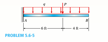
A cantilever beanie B is loaded by a uniform load q and a concentrated load P, as shown in the figure.
- Select the most economical steel C shape from Table F-3(a) in Appendix F; use q = 20 lb/ft and P = 300 lb (assume allowable normal stress is cra= IS ksi).
Note: For parts (a), (b), and (c), revise your initial beam selection as needed to include the distributed weight of the beam in addition to uniform load q.
(a)
The most economical steel
Answer to Problem 5.6.5P
The most economical steel
Explanation of Solution
Given information:
The uniform distributed load is
The following figure shows the free body diagram:
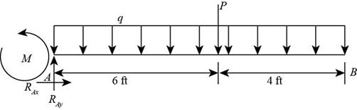
Figure-(1)
Write the expression for the maximum moment of beam.
Here, the load is
Write the expression for the section modulus.
Here, the maximum stress is
Write the expression for the maximum stress.
Here, the maximum stress is
Calculation:
Substitute
Substitute
Refer to the table
Substitute
Substitute
Here, the maximum stress is greater than the calculated stress, so we neglect this section.
Refer to the table
Substitute
Substitute
Hence, from the table “Appendix F” we will use the value
Conclusion:
The most economical steel
(b)
The most economical steel
Answer to Problem 5.6.5P
The most economical steel
Explanation of Solution
Given Information:
The uniform distributed load is
Write the expression for the maximum moment of beam.
Write the expression for the section modulus.
Write the expression for the maximum stress.
Calculation:
Substitute for
Substitute
Refer to the table
Substitute
Substitute
Here, the maximum stress is greater than the calculated stress, so we neglect this section.
Refer to the table
Substitute
Substitute
Hence, from the table “Appendix F” we will use the value
Conclusion:
The maximum value of load
(c)
The most economical steel
Answer to Problem 5.6.5P
The most economical steel
Explanation of Solution
Given Information:
The uniform distributed load is
Write the expression for the maximum moment of beam.
Write the expression for the section modulus.
Write the expression for the maximum stress.
Calculation:
Substitute
Substitute
Refer to the table
Substitute
Substitute
Hence, from the table “Appendix F” we will use the value
Conclusion:
The maximum value of load
Want to see more full solutions like this?
Chapter 5 Solutions
Mechanics of Materials, SI Edition


- A prospector uses a hand-powered winch (see figure) to raise a bucket of ore in his mine shaft. The axle of the winch is a steel rod of diameter d = 0.625 in. Also, the distance from the center of the axle to the center of the lifting rope is b = 4.0 in, If the weight of the loaded bucket is W = 100 lb, what is the maximum shear stress in the axle due to torsion? If the maximum bucket load is 125 lb and the allowable shear stress in the axle is 9250 psi, what is the minimum permissible axle diameter?arrow_forwardA curved bar ABC having a circular axis (radius r = 12 in.) is loaded by forces P = 400 lb (see figure). The cross section of the bar is rectangular with height h and thickness t. If the allowable tensile stress in the bar is 12,000 psi and the height A = 1.25 in., what is the minimum required thickness rmax?arrow_forwardA steel post (E=30×106) having thickness t = 1/8 in. and height L = 72 in. support a stop sign (see figure), where s = 12.5 in. The height of the post L is measured from the base to the centroid of the sign. The stop sign is subjected to wind pressure p = 20 lb/ft2 normal to its surface. Assume that the post is fixed at its base. What is the resultant load on the sign? (Sec Appendix E, Case 25, for properties of an octagon, n =8.) What is the maximum bending stress in the post? Repeat part (b) if the circular cut-outs arc eliminated over the height of the post.arrow_forward
- A stepped bar ACB with circular cross sections is held between rigid supports and loaded by an axial force P at midlength (see figure). The diameters for the two parts of the bar are d1= 20 ram and d2= 25 mm, and the material is elastoplastic with yield stress s = 250 MPs. Determine the plastic load Pp.arrow_forwardA brass sleeve S is fitted over a steel bolt B (see figure), and the nut is lightened until it is just snug. The bolt has a diameter dB= 25 mm, and the sleeve has inside and outside diameters d1= 26 mm and d2= 36 mm. respectively. Calculate the temperature rise .?T that is required to produce a. compressive stress of 25 MPa in the sleeve. (Use material properties as follows: for the sleeve, as= 21 × 10-6 /? and Es= 100 GPa; for the boll, aB= 10 × 10-6 /? and EB= 200Paarrow_forwardA ho 1 low st e el shaft ACB of outside diameter 50 mm and inside diameter 40 mm is held against rotation at ends A and B (see figure). Horizontal forces Pare applied at the ends of a vertical arm that is welded to the shaft at point C. Determine the allowable value of the forces P if the maximum permissible shear stress in the shaft is 45 MPa.arrow_forward
- A flat bar of width b and thickness t has a hole of diameter d drilled through it (see figure). The hole may have any diameter that will fit within the bar. What is the maximum permissible tensile load Pmaxif the allowable tensile stress in the material is st?arrow_forwardA hollow circular tube T of a length L = 15 in. is uniformly compressed by a force P acting through a rigid plate (see figure). The outside and inside diameters of the tube are 3.0 and 2.75 in., respectively. A concentric solid circular bar B of 1.5 in. diameter is mounted inside the lube. When no load is present, there is a clearance c = 0.0I0 in. between the bar B and the rigid plate. Both bar and tube are made of steel having an c[autoplastic stress-strain diagram with E = 29 X LO3 ksi and err= 36 ksi. (a) Determine the yield load Pt- and the corresponding shortening 3yof the lube. (b) Determine the plastic load Ppand the corresponding shortening Spof the tube. (c) Construct a load-displacement diagram showing the load Pas ordinate and the shortening 5 of the tube as abscissa. Hint: The load-displacement diagram is not a single straight line in the region 0 ^ P ^ Prarrow_forwardThe upper deck ala foothill stadium is supported by braces, each of which transfer a load P = 160 kips to the base of a column (see figure part a). A cap plate at the bottom of the brace distributes the load P to four flange pates (:1 = I in)t hrough a pin(d, = 2 in.) to two gusset plates t8 = l.5 in.) (see figure parts b and c). Determine the following quantities. (a) The average shear stress i in the pin. (b) The average bearing stress between the flange plates and the pin and also between the gusset plates and the pin Disregard friction between the plates. Determine the following quantities. (a) The average shear stress i in the pin. (b) The average bearing stress between the flange plates and the pin and also between the gusset plates and the pin (7j )L Disregard friction between the plates.arrow_forward
- A solid circular pole is subjected to linearly varying distributed force with maximum intensity q0at the base and an axial compressive load P at the top (see figure). Find the required diameter d of the pole if the maximum allowable normal stress is 150 M Pa. Let q0= 6.5 kN/m, P = 70 kN, and L = 3 m.arrow_forwardA steel cable with a nominal diameter of 25 mm (see Table 2-1) is used in a construction yard to lift a bridge section weighing 38 kN. as shown in the figure. The cable has an effective modulus of elasticity E = 140 GPa. (a) If the cable is 14 m long, how much will it stretch when the load is picked up? (b) If the cable is rated for a maximum load of 70 kN, that is the factor of safety with respect to failure of the cable?arrow_forwardThe flat bars shown in parts a and b of the figure are subjected to tensile forces P = 3.0 kips. Each bar a has thickness t = 0.25 in. (a) For the bar with a circular hole, determine the maximum stresses for hole diameters d = 1 in. and d = 2 in. if the width b = 6.0 in. (b) For the stepped bar with shoulder fillets, determine the maximum stresses for fillet radii R = 0.25 in. and R = 0.5 in. if the bar widths are b = 4.0 in. and c = 2.5 in.arrow_forward
 Mechanics of Materials (MindTap Course List)Mechanical EngineeringISBN:9781337093347Author:Barry J. Goodno, James M. GerePublisher:Cengage Learning