
Videos
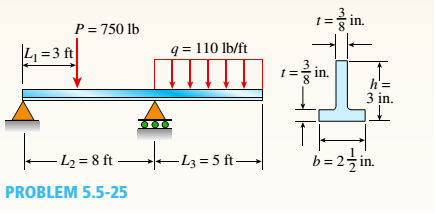
A beam with a T-section is supported and loaded as shown in the figure. The cross section has width b = 2 1/2 in., height c = 3 in., and thickness t = 3/8 in.
- Determine the maximum tensile and compressive stresses in the beam.
(a)
The maximum tensile stress.
The maximum compressive stress.
Explanation of Solution
Given information:
The uniform load is
The following figure shows the free body diagram of the beam.
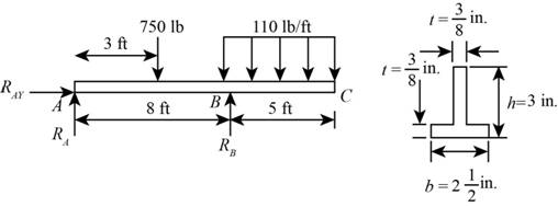
Figure-(1)
Write the expression for the distance of the neutral axis from the bottom layer.
Here, the width of the beam is
Write the expression for the distance of the neutral axis from the top layer.
Here, the distance of neutral axis from the top layer.
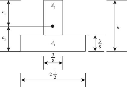
Figure-(2)
Write the expression for the moment of inertia.
Here, the moment of inertia is
Write the expression for the moment equilibrium about
Here, the reaction at point
Write the expression for the force equilibrium in vertical direction.
Here, the reaction at point
Write the expression for the maximum sagging moment at load
Here, the maximum sagging moment is
Write the expression for the maximum hogging moment at point
Here, the maximum hogging moment is
Write the expression for the maximum tensile stress at point
Here, the maximum tensile stress is
Write the expression for the maximum compressive stress at point
Here the maximum compressive stress is
Calculation:
Substitute
Substitute
Substitute
Substitute
Substitute
Substitute
Substitute
Substitute
Substitute
Conclusion:
The maximum tensile stress is
The maximum compressive stress is
(b)
The required depth of the beam.
Answer to Problem 5.5.25P
The required depth of the beam is
Explanation of Solution
Given Information:
The allowable stress in tension is
Write the expression for the maximum tensile stress at point
Write the expression for the distance of the neutral axis from the bottom layer.
Write the expression for the moment of inertia.
Calculation:
Substitute
Substitute
Substitute
. ......(XIII)
Substitute
Substitute
Conclusion:
The required depth of the beam is
Want to see more full solutions like this?
Chapter 5 Solutions
Mechanics of Materials, SI Edition


- A simple beam of span length 3.2 m carries a uniform load of intensity 48 kN/m, The cross section of the beam is a hollow box with wood flanges and steel side plates, as shown in the figure. The wood flanges are 75 mm x 100 mm in cross section, and the steel plates are 300 mm deep. What is the required thickness t of the steel plates if the allowable stresses are 120 M Pa for the steel and 6,5 M Pa for the wood? (Assume that the moduli of elasticity for the steel and wood are 210 GPa and 10 GPa, respectively, and disregard the weight of the beam.)arrow_forwardA beam with a wide-flange cross section (see figure) has the following dimensions: h = 120 mm, r = 10 mm, h = 300 mm, and /ij = 260 mm. The beam is simply supported with span length L = 3,0 im A concentrated load P = 120 kN acts at the midpoint of the span. At across section located 1.0 m from the left-hand support, determine the principal stresses tr, and tr2and the maximum shear stress Tmax at each of the following locations: (a) the top of the beam, (b) the top of the web, and (c) the neutral axisarrow_forwardA W 200 x 41.7 wide-flange beam (see Table F-l(b), Appendix F) is simply supported with a span length of 2.5 m (see figure). The beam supports a concentrated load of 100 kN at 0.9 m from support B. At a cross section located 0,7 m from the left-hand support, determine the principal stresses tr, and 2and the maximum shear stress rnMJt at each of the following locations: (a) the top of the beam, (b) the top of the web, and (c) the neutral axis,arrow_forward
- A wood beam reinforced by an aluminum channel section is shown in the figure. The beam has a cross section of dimensions 150 mm x 250 mm, and the channel has a uniform thickness of 6.5 mm. If the allowable stresses in the wood and aluminum are 8 M Pa and 38 M Pa, respectively, and if their moduli of elasticity are in the ratio 1 to 6, what is the maximum allowable bending moment for the beam?arrow_forwardA simple beam that is 18 ft long supports a uniform load of intensity q. The beam is constructed of two C8 x 11.5 sections (channel sections or C-shapes) on either side of a 4 × 8 (actual dimensions) wood beam (see the cross section shown in the figure part a). The modulus of elasticity of the steel (E; = 30,000 ksi) is 20 times that of the wood (Ew). (a) If the allowable stresses in the steel and wood are 12,000 psi and 900 psi, respectively, what is the allowable load qmax Note: Disregard the weight of the beam, and see Table F-3(a) of Appendix F for the dimensions and properties of the C-shape beam. (b) If the beam is rotated 90° to bend about its v axis (see figure part b) and uniform load q = 250 lb/ft is applied, find the maximum stresses trs and crw in the steel and wood, respectively Include the weight of the beam. (Assume weight densities of 35 lb/ft3 and 490 lb/ft3 for the wood and steel, respectively.)arrow_forwardA canti lever beam A B of a n isosceles t rapezoi-dal cross section has a length L = 0.8 m, dimensions bx= 80 mm and b2= 90 mm, and height h = 110 mm (see figure). The beam is made of brass weighing 85 kN/m3. Determine the maximum tensile stress asand maximum compressive stressarrow_forward
- A W 12 X 14 wide-flange beam (see Table F-l(a), Appendix F) is simply supported with a span length of 120 in. (see figure). The beam supports two anti-symmetrically placed concentrated loads of 7,5 kips each. At a cross section located 20 in. from the right-hand support, determine the principal stresses (7]and (7\ and the maximum shear stress Tmaw at each of the following locations: (a) the top of the beam, (b) the top of the web, and (c) the neutral axis,arrow_forwardThe cross section of a composite beam made of aluminum and steel is shown in the figure. The moduli of elasticity are TA= 75 GPa and Es= 200 GPa. Under the action of a bending moment that produces a maximum stress of 50 M Pa in the aluminum, what is the maximum stress xs in the steel? If the height of the beam remains at 120 mm and allowable stresses in steel and aluminum are defined as 94 M Pa and 40 M Pa, respectively, what heights h and h. arc required for aluminum and steel, respectively, so that both steel and aluminum reach their allowable stress values under the maximum moment?arrow_forwardA bimetallic beam used in a temperature-control switch consists of strips of aluminum and copper bonded together as shown in the figure, which is a cross-sectional view. The width of the beam is LO in,, and each strip has a thickness of 1/16 in. Under the action of a bending moment M = 12 lb-in, acting about the z axis, what are the maximum stresses aaand ecin the aluminum and copper, respectively? (Assume fA, = 10,5 x l0 psi and ecu= 16,8 × 10⁶ psi,)arrow_forward
- A W 12 x 50 steel wide-flange beam and a segment of a 4-inch thick concrete slab (see figure) jointly resist a positive bending moment of 95 kip-ft. The beam and slab are joined by shear connectors that are welded to the steel beam. (These connectors resist the horizontal shear at the contact surface.) The moduli of elasticity of the steel and the concrete are in the ratio 12 to 1. Determine the maximum stresses r1 and xtin the steel and concrete, respectively. Note: See Table F-l(a) of Appendix F for the dimensions and properties of the steel beam.arrow_forwardThe cross section of a beam made of thin strips of aluminum separated by a lightweight plastic is shown in the figure. The beam has width b = 3.0 in., the aluminum strips have thickness t = 0.1 in., and the plastic segments have heights d = 1.2 in. and 3d = 3.6 in. The total height of the beam is h = 6.4 in. The moduli of elasticity for the aluminum and plastic are EM= 11 X 106 psi and Ep= 440 X 10* psi, respectively. Determine the maximum stresses trAiand pin the aluminum and plastic, respectively, due to a bending moment of 6,0 kip-in.arrow_forwardA reinforced concrete slab (see figure) is reinforced with 13-mm bars spaced 160 mm apart at d = 105 mm from the top of the slab. The modulus of elasticity for the concrete is Ec= 25 GPa, while that of the steel is £s = 200 G Pa. Assume that allowable stresses for concrete and steel arecrac = 9.2 MPa and us = 135 MPa. l()5 mm Find the maximum permissible positive bending moment for a l-m wide strip of the slab. What is the required area of steel reinforcement, A^ if a balanced condition must be achieved? What is the allowable positive bending moment? (Recall that in a balanced design, both steel and concrete reach allowable stress values simultaneously under the design moment.)arrow_forward
 Mechanics of Materials (MindTap Course List)Mechanical EngineeringISBN:9781337093347Author:Barry J. Goodno, James M. GerePublisher:Cengage Learning