
Concept explainers
Videos
(a)
The capacitor voltage
Answer to Problem 5.71HP
The value of the capacitor voltage
Explanation of Solution
Calculation:
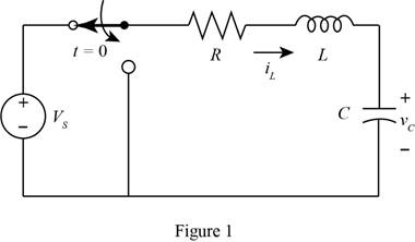
The given diagram is shown in Figure 1
For time
The required diagram is shown in Figure 2
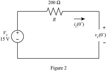
From above, the expression for the initial voltage across the capacitor is given by,
The expression for the voltage across the capacitor for time
Substitute
Conclusion:
Therefore, the value of the capacitor voltage
(b)
The capacitor voltage
Answer to Problem 5.71HP
The value for the voltage across the capacitor at time
Explanation of Solution
Calculation:
The conversion from
The conversion from
The expression for the current flowing through the inductor for time
The inductor opposes sudden change in the current, thus the current
Substitute
Mark the values and redraw the diagram for time
The required diagram is shown in Figure 3
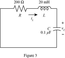
Apply KVL in the above circuit.
The standard second order equation for the differential equation.
From above and from equation (1), the angular frequency is derived as,
Substitute
The expression for the damping coefficient is given by,
Substitute
The value of
The expression to calculate the damping frequency of the circuit is given by,
Substitute
The expression for the output response of the capacitor is given by,
Substitute
Substitute
Substitute
The differentiation of equation (3) with respect to
Substitute
The expression for the current through the inductor and the capacitor is same and is given by,
Substitute
Substitute
Substitute
Substitute
Substitute
Conclusion:
Therefore, the value for the voltage across the capacitor at time
(c)
The capacitor voltage
Answer to Problem 5.71HP
The final voltage across the capacitor for the time
Explanation of Solution
Calculation:
For time
The required diagram is shown in Figure 4
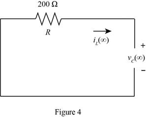
From the above circuit, the circuit is source free and the final voltage across the capacitor is given by,
Conclusion:
Therefore, the final voltage across the capacitor for the time
(d)
The value of maximum capacitor voltage.
Answer to Problem 5.71HP
The value of maximum capacitor voltage is
Explanation of Solution
Calculation:
The maximum capacitor voltage is obtained by evaluating the expression for voltage across the capacitor equal to zero and is given by,
Substitute
Solve further as,
Substitute
Conclusion:
Therefore, the value of maximum capacitor voltage is
Want to see more full solutions like this?
Chapter 5 Solutions
EBK PRINCIPLES AND APPLICATIONS OF ELEC


- Suppose we have a capacitance C discharging through a resistance R. Define and give an expression for the time constant. To attain a long time constant, do we need large or small values for R? For C?arrow_forwardDraw the Thévenin and Norton equivalent circuits for Figure P5.91, labeling the elements and terminals.arrow_forwardAn 8 μF capacitor is a 200 V DC in series with a 0.5 MΩ resistorlinked to the source. According to this;a) τ =?b) Initial value of charging currentc) The time required for the voltage at the capacitor ends to become 160 V.d) 4 s after connecting to the source, i =? and Vc =? Calculate the values.arrow_forward
- Which of the following is true regarding the behavior of capacitors when energized by a DC source? a. At transient state, the capacitor behaves as an open circuit. b. At transient state, the capacitor behaves as a short circuit. c. At steady-state, the capacitor behaves as a short circuit. d. At steady-state, the capacitor behaves as an open circuit.arrow_forwardDetermine the power for each source shown in Figure P5.76. Also, state whether each source is delivering or absorbing energy.arrow_forwardAssuming that a nonzero ac voltage source is applied, what can you say about whether the power and reactive power are positive, negative, or zero for a pure capacitance in series with a pure inductance? Consider cases in which the impedance magnitude of the capacitance is greater than, equal to, or less than the impedance magnitude of the inductance. Repeat Problem P5.74 for the inductance and capacitance in parallel.arrow_forward
- What current flows through an ideal capacitor if the voltage across the capacitor is constant with time? To what circuit element is an ideal capacitor equivalent in circuits for which the currents and voltages are constant with time?arrow_forwardIn the first method to write the equation, why is the capacitor value not included in the equation at first?arrow_forwardWhen charging a capacitor, as discussed in conjunction with Figure , how long does it take for the voltage on the capacitor to reach emf? Is this a problem?arrow_forward
- How does the product rule of differentiation (differential calculus) useful in Capacitance and Capacitors in Series and Parallel Connections?arrow_forwardSolve for the mesh currents shown in Figure P5.54.arrow_forwardWhat is the practical application of a circuit that you can tune such that it reaches some minimum resistance? Would there be an application to being able to tune where that minimum occurs, by changing the capacitance or inductance of the circuit?arrow_forward
 Introductory Circuit Analysis (13th Edition)Electrical EngineeringISBN:9780133923605Author:Robert L. BoylestadPublisher:PEARSON
 Delmar's Standard Textbook Of ElectricityElectrical EngineeringISBN:9781337900348Author:Stephen L. HermanPublisher:Cengage Learning
 Programmable Logic ControllersElectrical EngineeringISBN:9780073373843Author:Frank D. PetruzellaPublisher:McGraw-Hill Education
 Fundamentals of Electric CircuitsElectrical EngineeringISBN:9780078028229Author:Charles K Alexander, Matthew SadikuPublisher:McGraw-Hill Education
 Electric Circuits. (11th Edition)Electrical EngineeringISBN:9780134746968Author:James W. Nilsson, Susan RiedelPublisher:PEARSON
 Engineering ElectromagneticsElectrical EngineeringISBN:9780078028151Author:Hayt, William H. (william Hart), Jr, BUCK, John A.Publisher:Mcgraw-hill Education,