
PROGRAMMABLE LOGIC CONTROLLERS(LL)-PKG.
5th Edition
ISBN: 9781260535044
Author: Petruzella
Publisher: MCG
expand_more
expand_more
format_list_bulleted
Videos
Textbook Question
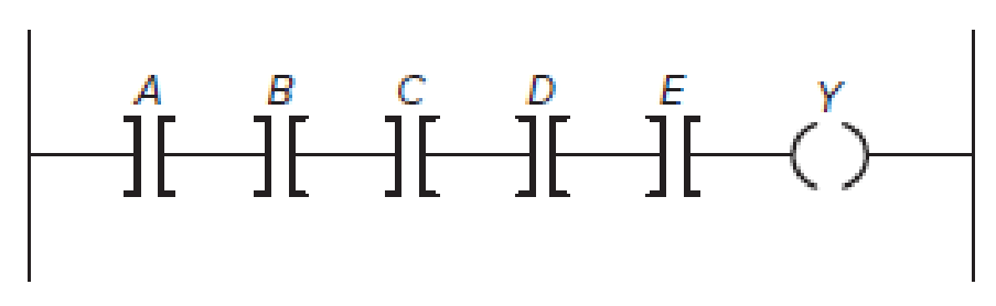
Chapter 5, Problem 5P
Redraw the
Expert Solution & Answer
Want to see the full answer?
Check out a sample textbook solution
Students have asked these similar questions
Design the simplest circuit that has three inputs, a, b, and c, which returns an output value of 1 whenever g and b are complements of each other or b and c are complements of each other, otherwise the output is 0.
Realize the circuit using 4input , 3output PAL
The input of an IC requires a constant 5 V, but the supply voltage is 9 V. Use thevoltage divider equations to create a voltage divider with an output of 5 V. Assumethe IC has such a high input resistance (10 MΩ) that it practically draws nocurrent from the divider.
Draw the circuit diagram to output F given in the expression above by referring to schematics for 2-2) and 2-3). Use the space below to draw both the IC with pin assignments and a circuit schematic.
Using a single 7400 IC construct a circuit to output the following Boolean function:
F = AB + CD
Chapter 5 Solutions
PROGRAMMABLE LOGIC CONTROLLERS(LL)-PKG.
Ch. 5 - What does the memory map for a typical PLC...Ch. 5 - Compare the function of the PLC program and data...Ch. 5 - Prob. 3RQCh. 5 - Prob. 4RQCh. 5 - a. What information is stored in the input image...Ch. 5 - a. What information is stored in the output image...Ch. 5 - Prob. 7RQCh. 5 - List four factors that enter into the length of...Ch. 5 - Prob. 9RQCh. 5 - Prob. 10RQ
Ch. 5 - Prob. 11RQCh. 5 - Answer the following with regard to the Examine If...Ch. 5 - Answer the following with regard to the Examine If...Ch. 5 - Answer the following with regard to the Output...Ch. 5 - A normally closed pushbutton is connected to a PLC...Ch. 5 - Prob. 16RQCh. 5 - Prob. 17RQCh. 5 - Prob. 18RQCh. 5 - Prob. 19RQCh. 5 - Prob. 20RQCh. 5 - Prob. 21RQCh. 5 - Explain the purpose of Windows based programming...Ch. 5 - Prob. 23RQCh. 5 - Prob. 24RQCh. 5 - Prob. 25RQCh. 5 - Prob. 26RQCh. 5 - Assign each of the following discrete input and...Ch. 5 - Prob. 2PCh. 5 - Prob. 3PCh. 5 - Redraw the program shown in Figure 5-57 corrected...Ch. 5 - Redraw the program shown in Figure 5-58 corrected...Ch. 5 - Prob. 6PCh. 5 - Prob. 7PCh. 5 - Prob. 8PCh. 5 - Write the ladder logic program needed to implement...
Knowledge Booster


Learn more about
Need a deep-dive on the concept behind this application? Look no further. Learn more about this topic, computer-science and related others by exploring similar questions and additional content below.Similar questions
- In verilog a counter must be developed from 0 to 9999 with a reset and parallel loading. The reset will be a button in charge of returning the count to 0 when pressed.For this practice, the implemented circuit will only use a 7-segment BCD converter module, which will have to be managed between the different 7-segment displays at a given frequency.arrow_forwardDiscuss the Interface LED using General Purpose Input Output (GPIO) port. Investigate in further detail the operation of the GPIO ports on the MSP430F5529 Use control logic to manipulate outputs.arrow_forwardDraw the circuit and obtain the truth table of the VHDL module below module SAM(a, b, c, M, S);input a,b,c;output M;output S;wire d,e,f;xor(S,a,b,c);and(d,~a,b);and(e,b,c);and(f,~a,c);or(M,d,e,f);endmodulearrow_forward
- 3) Comment on the functionality of the two circuits given in Figures 1.7 and 1.8.arrow_forwardCreate a sequential circuit (in Logisim, preferably) which displays the integers 0 to 9 using four D-flipflops(rising-edge triggered), one GND pin, one clock input, one BCD to 7-segment LED decoder,and one 7-segment LED. The 4-bit counter must count-up.arrow_forwardDesign a two-bit counter (sequential circuit) using falling edge triggered T-flipflops, with one input line x. When x= 1, the state of the circuit remains the same. When x = 0, the circuit goes through the state transitions byincrementing the state count, i.e., from 00 to 01, 01 to 10, 10 to 11, and 11 to 00, and repeats. Draw circuit diagramof the designed counter. if z=83,Convert z to Base-2, e.g., z= (156)10 = (10011100)2.Provide this bitstream as input to K and draw the timing diagram of the outputs of both the T-flipflops.arrow_forward
- Write basic issues architeure circuitarrow_forwardA circuit using 3 counters C1, C2 and C3 is shown below, the time of a complete cycle is 1 second to run all over the program and return to first rung . 1/explain how it is working and plot the inputs/outputs in function of time. 2/ deduce the operational purpose of this circuitarrow_forwardIdentify the state diagram operation and find its output sequence for the following input sequence X=0101-1100-101-0000 the circuit accepts input bits from LSB to MSBarrow_forward
- Given the following Combinational circuit, Use Verilog HDL on Quartus tool to1. Write a Verilog HDL code to describe the module DCDR2×4 // this module name must be your last name ( younis2. Write a Verilog HDL code to describe the whole system structurally from its subsystems// this module name must be your university number ( 1181230)arrow_forwardDesign an appropriate combinational circuit that implements a digital system with the following output functions an AC remote: ON, OFF, MODE, SHIFT, FAN, SMART, SWING, ECO using a decoder.arrow_forwardTopic: Flip Flop ApplicationTrace the operation of the following sequential circuits, by drawing the timing diagram and creating the complete count sequence. (Note: Start at 0 initial state)arrow_forward
arrow_back_ios
SEE MORE QUESTIONS
arrow_forward_ios
Recommended textbooks for you
 Systems ArchitectureComputer ScienceISBN:9781305080195Author:Stephen D. BurdPublisher:Cengage Learning
Systems Architecture
Computer Science
ISBN:9781305080195
Author:Stephen D. Burd
Publisher:Cengage Learning
Pressure Sensors with Display; Author: Balluff Worldwide;https://www.youtube.com/watch?v=HqAV2xjCLxE;License: Standard Youtube License