Concept explainers
Plot the shear diagram, bending moment diagram, axial force diagram, and the qualitative deflected shape of the frame.
Explanation of Solution
Write the condition for static instability, determinacy and indeterminacy of plane frames as follows:
Here, number of members is m, number of external reactions is r, the number of joints is j, and the number of elastic hinges is
Find the degree of static indeterminacy (i) using the equation;
Refer to the Figure in the question;
The number of members (m) is 2.
The number of external reactions (r) is 3.
The number of joints (j) is 3.
The number of elastic hinges
Substitute the values in Equation (2);
Show the free-body diagram of the entire frame as in Figure 1.
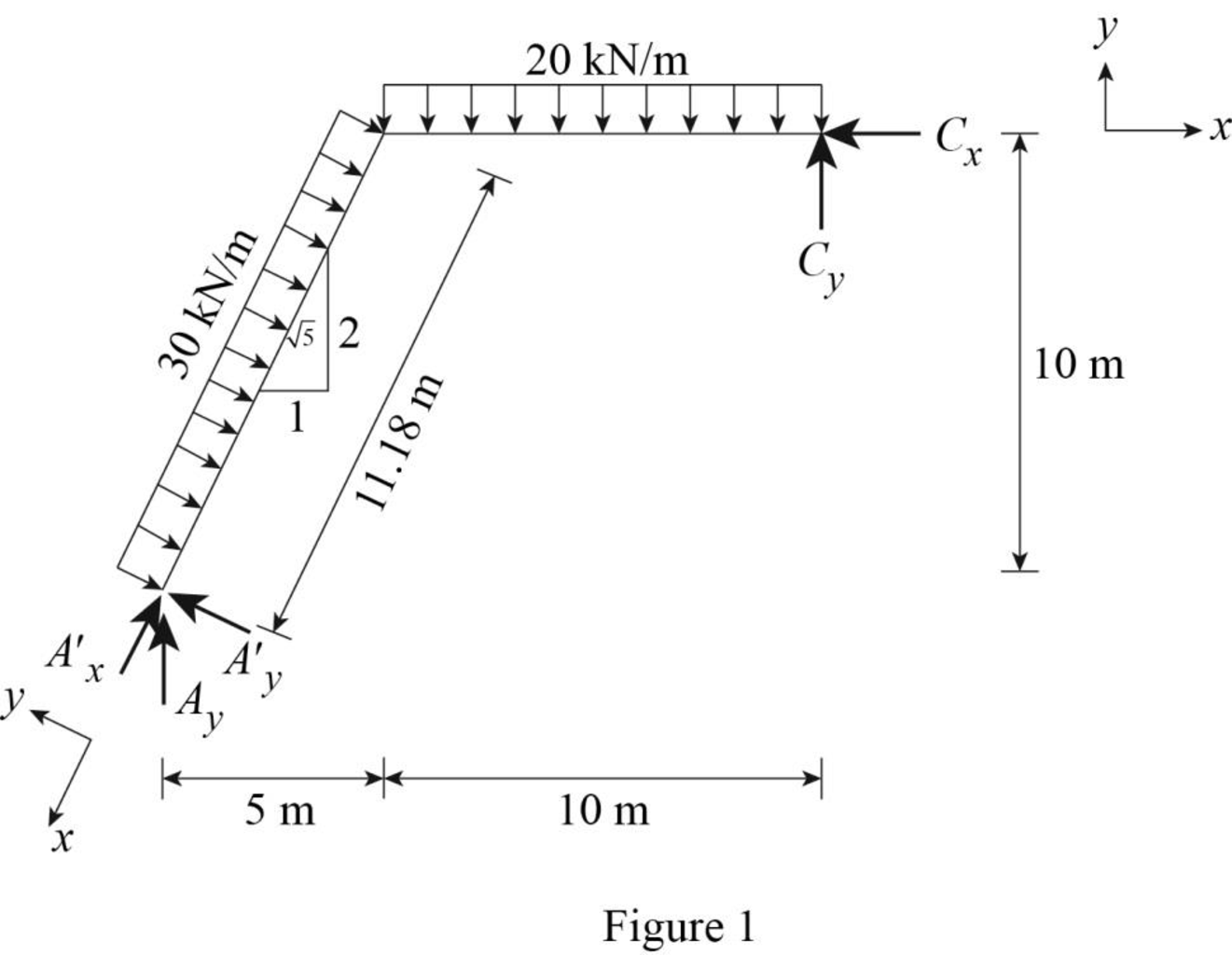
Refer Figure (1).
Find the distance for the beam AB.
Find the horizontal reaction at point C by resolving the horizontal component of forces.
Find the resultant reaction at point C by taking moment about point A.
Find the vertical reaction at point A by resolving the vertical component of forces.
Consider point A:
Resolve the vertical component of forces.
Resolve the horizontal component of forces.
Show the free-body diagram of the members and joints of the entire frame as in Figure 2.
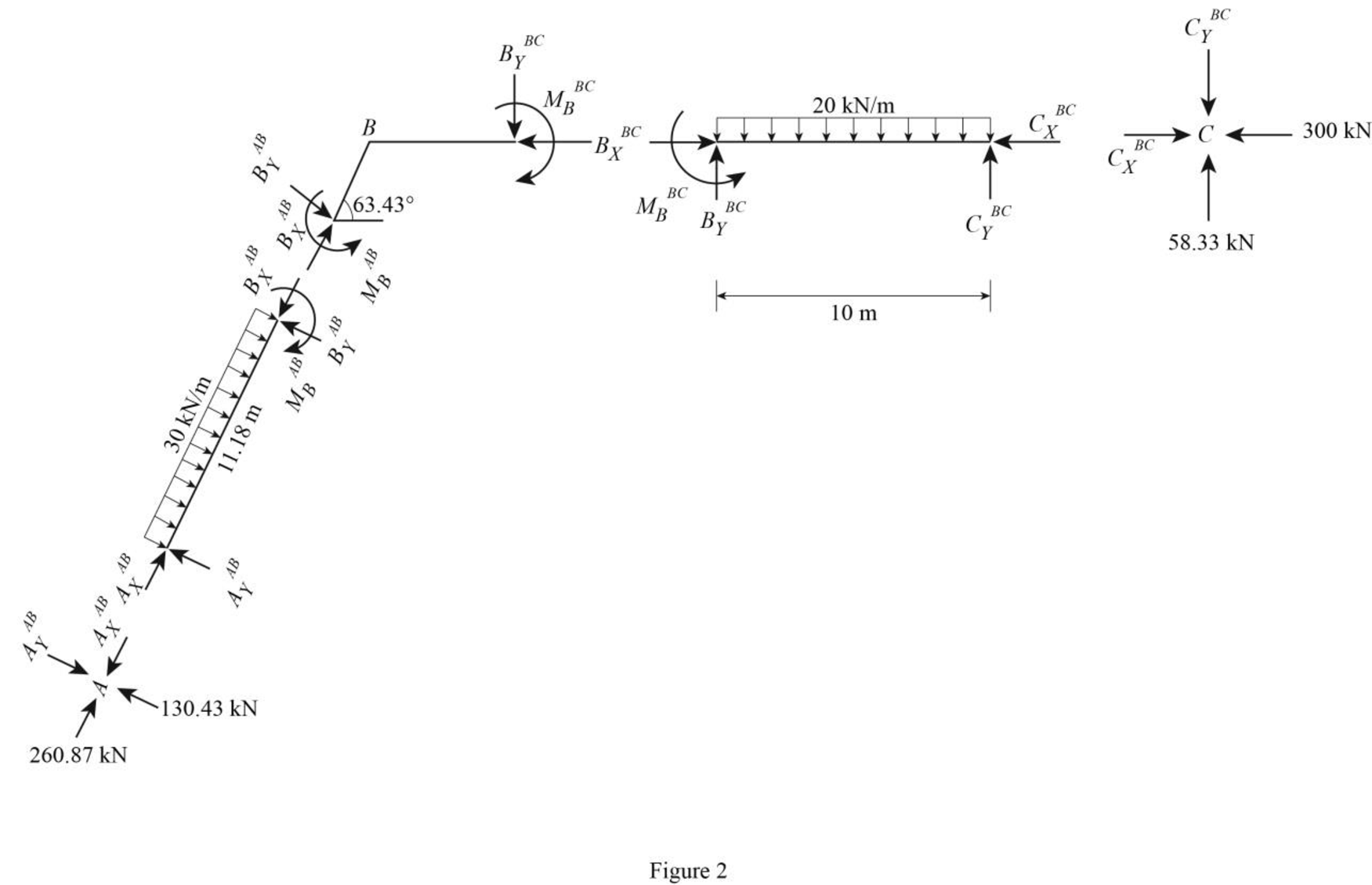
Consider point A:
Resolve the vertical component of forces.
Resolve the horizontal component of forces.
Consider the member AB:
Resolve the vertical component of forces.
Resolve the horizontal component of forces.
Take moment about the point B.
Consider the point C:
Resolve the vertical component of forces.
Resolve the horizontal component of forces.
Consider the member BC:
Resolve the vertical component of forces.
Resolve the horizontal component of forces.
Take moment about point B:
Plot the moment end forces of the frame as in Figure 3.
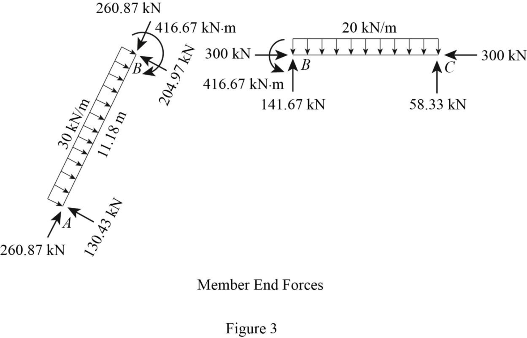
Refer to the moment end force diagram plot the shear diagram, bending moment diagram, and the axial force diagrams.
Plot the shear force diagram as in Figure 4.
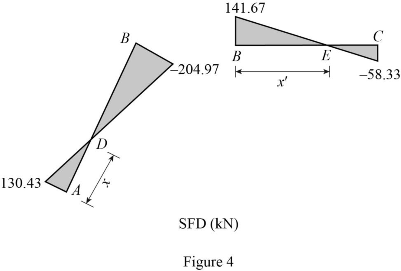
The maximum bending moment occurs where the shear force changes sign.
Consider the section ADB, use the similar triangle concept.
Find the maximum bending at point D.
Consider the section BEC, use the similar triangle concept.
Find the maximum bending at point D.
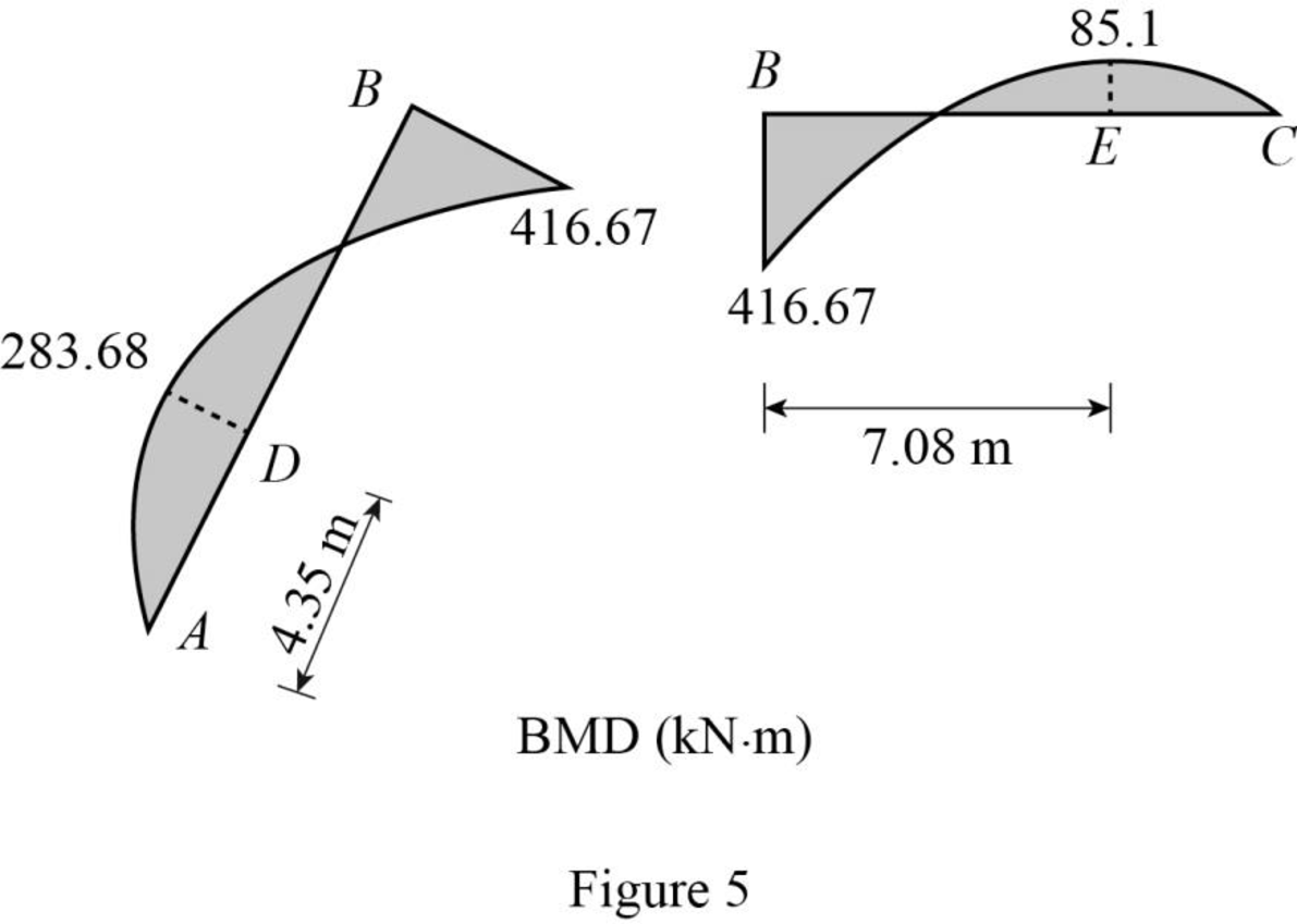
Plot the bending moment diagram as in Figure 5.
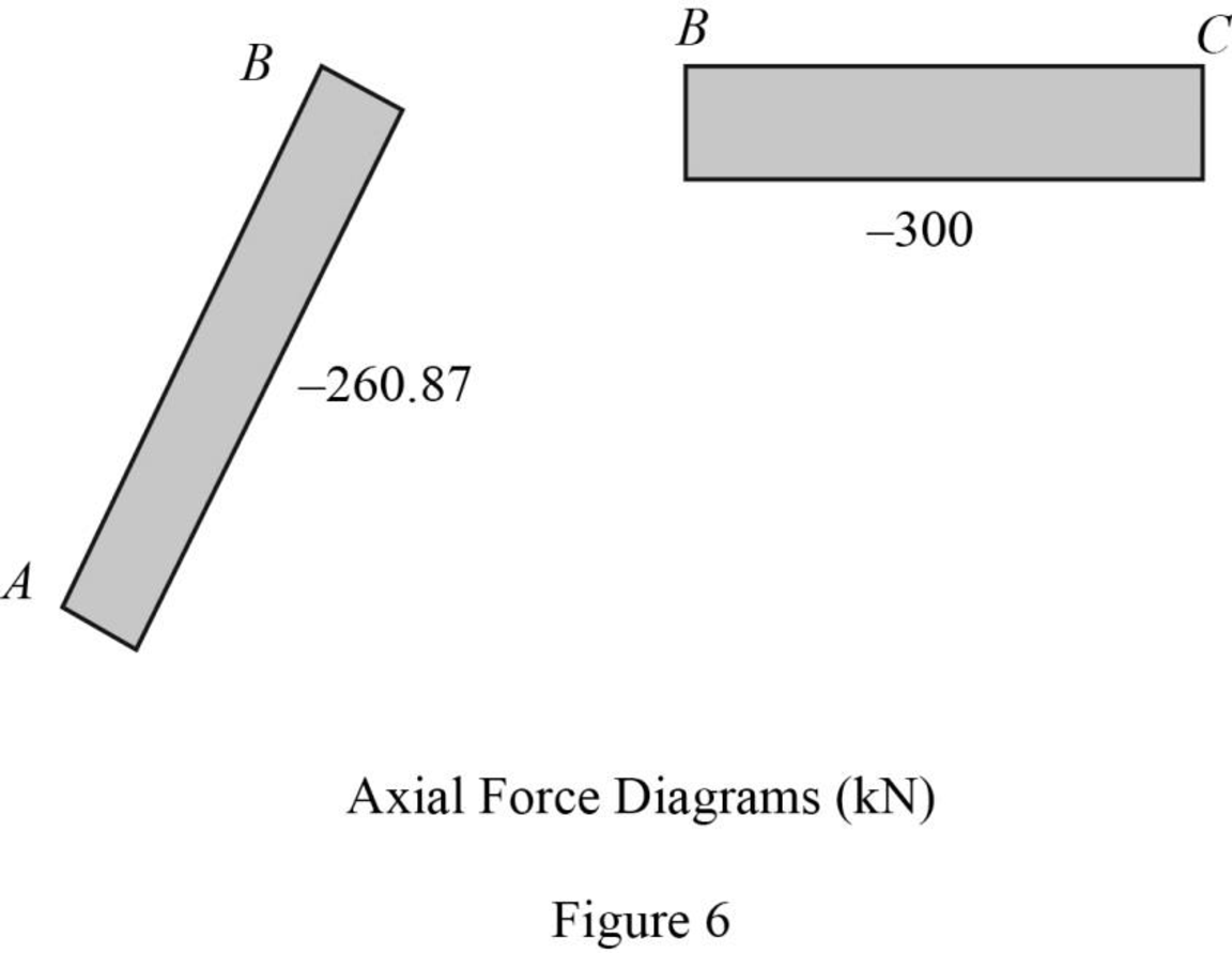
Plot the axial force diagram as in Figure 6.
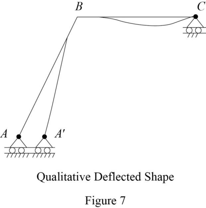
Plot the qualitative deflected shape as in Figure 7.
Want to see more full solutions like this?
Chapter 5 Solutions
Structural Analysis, Si Edition


- Use the unit load method to find the magnitude and direction of the deflection of the joint Cin the truss shown in Fig., P.15.11. All members have a cross-sectional area of 500 mm² and a Young's modulus of 200 000 N/mm². Ans. 23.4 mm, 9.8° to left of vertical.arrow_forward1. Draw the shear and moment diagram of the beam below using equation method. 6.9 The intensity of the distributed load on the simply supported beam varies lin- early from zero to wo. (a) Derive the equation of the elastic curve. (b) Find the loca- tion of the maximum deflection. Express answer in terms of El. A 6m FIG.P6.9 Wo=14kN/m B Xarrow_forward6.14 through 6.17 use the moment area method to determine the slopes and deflections at points B and C of the beam shown.arrow_forward
- M В Determine the equations for slope and deflection of the beam shown by the direct integration method. EI = constant. FIG. P6.1arrow_forwardThe truss shown in Fig.3 is supported by a roller at C and a hinge at D. Use Castigliano's theorem to calculate the horizontal deflection for point B. E-200 B. kN/mm² and A-800 mm² for all members. s) 15 kN 2 m 20 KN B Th 2 m Fig.3arrow_forwardDETERMINE THE EXTERNAL REACTIONS AT FIXED SUPPORT AND SLOPE AND DEFLECTION AT MIDSPAN OF SEGMENT BC OF THE BEAM SHOWN USING CONJUGATE BEAM METHODarrow_forward
