
Statics and Mechanics of Materials - Modified Access
5th Edition
ISBN: 9780134392363
Author: HIBBELER
Publisher: PEARSON
expand_more
expand_more
format_list_bulleted
Concept explainers
Videos
Textbook Question
Chapter 5.3, Problem 4FP
Determine the greatest load P that can be applied to the truss so that none of the members are subjected to a force exceeding either 2 kN in tension or 1.5 kN in compression.
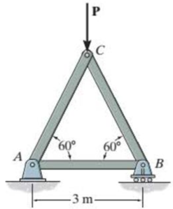
Prob. F5-4
Expert Solution & Answer
Want to see the full answer?
Check out a sample textbook solution
Students have asked these similar questions
The mobile crane is symmetrically supported by two outriggers at A and B to relieve the suspension of the vehicle on which it sits and to provide extra stability. Determine the vertical reactions at each of the two outriggers as a function of boom angle when the boom is carrying a 1.2 Mg load and the crane and truck have a combined mass of 18 Mg and the boom has a mass of 2 Mg. 0 = 45°
Determine the force in each member of the truss and state if the members are in tension or compression. Set P1 = 9 kN, P2 = 15 kN. using the principle of static equilibrium of moments
Determine the force in each member of the loaded truss. The forces are positive if in tension, negative if in compression.Assume F = 2910 N, a = 1.8 m, b = 3.6 m, θ= 40°.
Chapter 5 Solutions
Statics and Mechanics of Materials - Modified Access
Ch. 5.3 - In each ease, calculate the support reactions and...Ch. 5.3 - Identify the zero-force members in each truss....Ch. 5.3 - Determine the force in each member of the truss...Ch. 5.3 - Determine the force in each member of the truss...Ch. 5.3 - Determine the force in each member of the truss...Ch. 5.3 - Determine the greatest load P that can be applied...Ch. 5.3 - Identify the zero-force members in the truss....Ch. 5.3 - Determine the force in each member of the truss...Ch. 5.3 - Determine the force in each member of the truss...Ch. 5.3 - Determine the force in each member of the truss...
Ch. 5.3 - Determine the force in each member of the truss...Ch. 5.3 - Determine the force in each member of the truss...Ch. 5.3 - Determine the force in each member of the truss,...Ch. 5.3 - Determine the force in each member of the truss,...Ch. 5.3 - Determine the force in each member of the truss...Ch. 5.3 - Determine the force in each member of the truss in...Ch. 5.3 - Members AB and BC can each support a maximum...Ch. 5.3 - Members AB and BC can each support a maximum...Ch. 5.3 - Determine the force in each member of the truss...Ch. 5.3 - If the maximum force that any member can support...Ch. 5.3 - Determine the force in each member of the truss...Ch. 5.3 - Determine the force in each member of the truss...Ch. 5.3 - Determine the force in each member of the truss...Ch. 5.3 - Determine the force in each member of the truss...Ch. 5.4 - Determine the force in members BC, CF, and FE and...Ch. 5.4 - Determine the force in members LK, KC, and CD of...Ch. 5.4 - Determine the force in members KJ, KD, and CD of...Ch. 5.4 - Determine the force in members EF, CF, and BC of...Ch. 5.4 - Determine the force in members GF, GD, and CD of...Ch. 5.4 - Determine the force in members DC, HI, and JI of...Ch. 5.4 - Determine the force in members DC, HC and HI of...Ch. 5.4 - Determine the force in members ED, EH, and GH of...Ch. 5.4 - Determine the force in members HG, HE, and DE of...Ch. 5.4 - Determine the force in members CD, HI, and CH of...Ch. 5.4 - Determine the force in members CD, CJ, KJ, and DJ...Ch. 5.4 - Prob. 22PCh. 5.4 - The Howe truss is subjected to the loading shown....Ch. 5.4 - The Howe truss is subjected to the loading shown....Ch. 5.4 - Determine the force in members EF, CF, and BC, and...Ch. 5.4 - Determine the force in members AF, BF, and BC, and...Ch. 5.4 - Prob. 27PCh. 5.4 - Determine the force in members BC, BE, and EF of...Ch. 5.4 - Prob. 29PCh. 5.4 - Determine the force in members CD, CF, and CG and...Ch. 5.4 - Determine the force developed in members FE, EB,...Ch. 5.5 - In each ease, identify any two-force members, and...Ch. 5.5 - F5-13. Determine the force P needed to hold the...Ch. 5.5 - Determine the horizontal and vertical components...Ch. 5.5 - If a 100-N force is applied to the handles of the...Ch. 5.5 - Determine the horizontal and vertical components...Ch. 5.5 - Determine the force P required to hold the 100-lb...Ch. 5.5 - In each case, determine the force P required to...Ch. 5.5 - Determine the force P required to hold the 50-kg...Ch. 5.5 - Determine the force P required to hold the 150-kg...Ch. 5.5 - Determine the reactions at the supports A, C, and...Ch. 5.5 - Determine the resultant force at pins A, B, and C...Ch. 5.5 - Determine the reactions at the supports at A, E,...Ch. 5.5 - The wall crane supports a load of 700 lb....Ch. 5.5 - The wall crane supports a load of 700 lb....Ch. 5.5 - Determine the horizontal and vertical components...Ch. 5.5 - Determine the force in members FD and DB of the...Ch. 5.5 - Determine the force that the smooth 20-kg cylinder...Ch. 5.5 - The three power lines exert the forces shown on...Ch. 5.5 - The pumping unit is used to recover oil. When the...Ch. 5.5 - Determine the force that the jaws J of the metal...Ch. 5.5 - Prob. 47PCh. 5.5 - Prob. 48PCh. 5.5 - Prob. 49PCh. 5.5 - Determine the force created in the hydraulic...Ch. 5.5 - The hydraulic crane is used to lift the 1400-lb...Ch. 5.5 - Determine force P on the cable if the spring is...Ch. 5.5 - Prob. 53PCh. 5.5 - Prob. 54PCh. 5.5 - Prob. 55PCh. 5.5 - Determine the force P on the cable if the spring...Ch. 5.5 - Prob. 57PCh. 5.5 - Prob. 58PCh. 5.5 - Prob. 59PCh. 5.5 - Prob. 60PCh. 5.5 - The platform scale consists of a combination of...Ch. 5 - All the problems solutions must include FBDs....Ch. 5 - Determine the force in each member of the truss...Ch. 5 - Determine the force in member GJ and GC of the...Ch. 5 - Determine the force in members GF, FB, and BC of...Ch. 5 - Prob. 5RPCh. 5 - Determine the horizontal and vertical components...Ch. 5 - Prob. 7RPCh. 5 - Determine the resultant forces at pins B and C on...
Knowledge Booster


Learn more about
Need a deep-dive on the concept behind this application? Look no further. Learn more about this topic, mechanical-engineering and related others by exploring similar questions and additional content below.Similar questions
- Determine the force in each member of the loaded truss. The forces are positive if in tension, negative if in compression. Assume F= 2100 N.a = 1.6 m. b= 32m. =45°arrow_forwardThe rigid bar is supported by the two short white spruce wooden posts and a spring. If each of the posts has an unloaded length of 1 m and a cross-sectional area of 600 mm2, and the spring has a stiffness of k = 2 MN >m and an unstretched length of 1.02 m, determine the force in each post after the load is applied to the bar.arrow_forwardThe three A-36 steel wires each have a diameter of 2 mm and unloaded lengths of LAC = 1.60 m and LAB = LAD = 2.00 m. Determine the force in each wire after the 150-kg mass is suspended from the ring at A.arrow_forward
- The post is made from 606l-T6 aluminum and has a diameter of 50 mm. It is fixed supported at A and B, and at its center C there is a coiled spring attached to the rigid collar. If the spring is originally uncompressed, determine the reactions at A and B when the force P = 40 kN is applied to the collar.arrow_forwardDetermine the greatest force P that can be applied to the truss so that none of the members are subjected to a force exceeding either 4.5 kN in tension or 3 kN in compression.arrow_forwardThe jib crane is supported by a pin at C and rod AB. If the load has a mass of 1.89 Mg with its center of mass located at G. If x = 5 m, determine the following: 9.1 The force developed in rod AB on the crane is Blank 1 kN. 9.2 The support reaction at pin C is Blank 2 kN. 9.3 The jib crane is supported by a pin at C and rod AB. The rod can withstand a maximum tension of 38 kN. If the load has a mass of 2 Mg, with its center of mass located at G, determine the maximum allowable distance x in meters.arrow_forward
- Determine the tension developed in cables OD and OB and the strut OC, required to support the 50-kg crate. The spring OA has an unstretched length of 0.8 m and stiffness kOA = 1.2 kN/m The force in the strut acts along the axis of the strut.arrow_forwardDetermine the force in members FG, FH, and HG of the truss which serves to support the deck of a bridge if P1 = 50kN, P2 = 20kN and P3 = 10kN. State if these members are in tension or compression.arrow_forwardUsing the attached image, determine the force in each member of the truss and state if the members are in tension or compression. Set P1= 2 kN and P2= 1.5 kN. Use method of joint.arrow_forward
- Determine the force in member 2 of the assembly as shown if the support at joint 1 settles downward 25 mm. Take AE = 8(103) kN.arrow_forwardDetermine the reactions at the supports of the truss structure. Set P1 = 6 kN andP2 = 9 kN.arrow_forwardThe A-36 steel wires AB and AD each have a diameter of 2 mm and the unloaded lengths of each wire are LAC = 1.60 m and LAB = LAD = 2.00 m. Determine the required diameter of wire AC so that each wire is subjectedto the same force when the 150-kg mass is suspended from the ring at A.arrow_forward
arrow_back_ios
SEE MORE QUESTIONS
arrow_forward_ios
Recommended textbooks for you
 Elements Of ElectromagneticsMechanical EngineeringISBN:9780190698614Author:Sadiku, Matthew N. O.Publisher:Oxford University Press
 Mechanics of Materials (10th Edition)Mechanical EngineeringISBN:9780134319650Author:Russell C. HibbelerPublisher:PEARSON
 Thermodynamics: An Engineering ApproachMechanical EngineeringISBN:9781259822674Author:Yunus A. Cengel Dr., Michael A. BolesPublisher:McGraw-Hill Education
 Control Systems EngineeringMechanical EngineeringISBN:9781118170519Author:Norman S. NisePublisher:WILEY
 Mechanics of Materials (MindTap Course List)Mechanical EngineeringISBN:9781337093347Author:Barry J. Goodno, James M. GerePublisher:Cengage Learning
 Engineering Mechanics: StaticsMechanical EngineeringISBN:9781118807330Author:James L. Meriam, L. G. Kraige, J. N. BoltonPublisher:WILEY
Elements Of Electromagnetics
Mechanical Engineering
ISBN:9780190698614
Author:Sadiku, Matthew N. O.
Publisher:Oxford University Press
Mechanics of Materials (10th Edition)
Mechanical Engineering
ISBN:9780134319650
Author:Russell C. Hibbeler
Publisher:PEARSON
Thermodynamics: An Engineering Approach
Mechanical Engineering
ISBN:9781259822674
Author:Yunus A. Cengel Dr., Michael A. Boles
Publisher:McGraw-Hill Education
Control Systems Engineering
Mechanical Engineering
ISBN:9781118170519
Author:Norman S. Nise
Publisher:WILEY
Mechanics of Materials (MindTap Course List)
Mechanical Engineering
ISBN:9781337093347
Author:Barry J. Goodno, James M. Gere
Publisher:Cengage Learning
Engineering Mechanics: Statics
Mechanical Engineering
ISBN:9781118807330
Author:James L. Meriam, L. G. Kraige, J. N. Bolton
Publisher:WILEY
EVERYTHING on Axial Loading Normal Stress in 10 MINUTES - Mechanics of Materials; Author: Less Boring Lectures;https://www.youtube.com/watch?v=jQ-fNqZWrNg;License: Standard YouTube License, CC-BY