Videos
Solve Prob. 5.85, assuming that the cross section of the beam is inverted, with the flange of the beam resting on the supports at B and C.
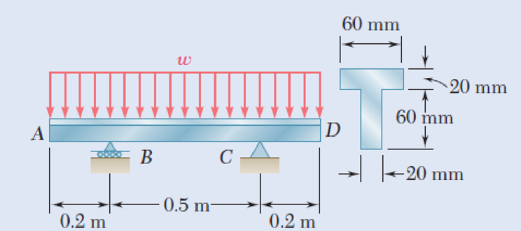
5.85 Determine the largest permissible distributed load w for the beam shown, knowing that the allowable normal stress is +80 MPa in tension and –130 MPa in compression.
Fig. P5.85
The largest permissible distributed load w.
Answer to Problem 86P
The largest permissible distributed load (w) is
Explanation of Solution
Given information:
The allowable normal stress of the material in tension is
The allowable normal stress of the material in compression is
Calculation:
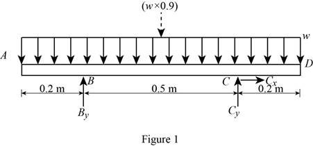
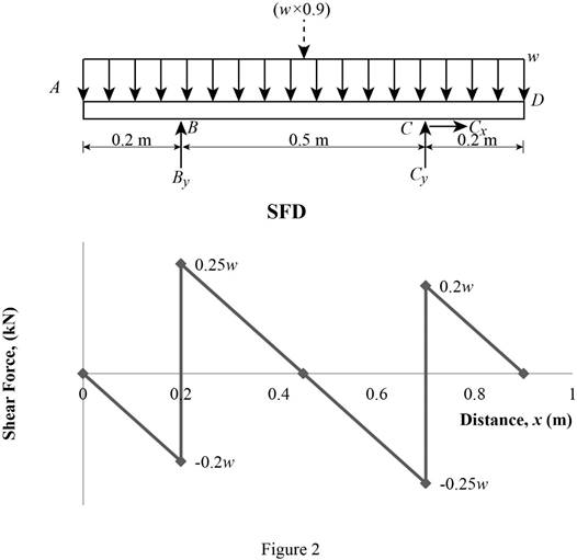
Show the free-body diagram of the beam as in Figure 1.
Determine the vertical reaction at point C by taking moment about point B.
Determine the vertical reaction at point B by resolving the vertical component of forces.
Shear force:
Show the calculation of shear force as follows;
Show the calculated shear force values as in Table 1.
| Location (x) m | Shear force (V) kN |
| A | 0 |
| B (Left) | –0.2w |
| B (Right) | 0.25w |
| C (Left) | –0.25w |
| C (Right) | 0.2w |
| D | 0 |
Plot the shear force diagram as in Figure 2.
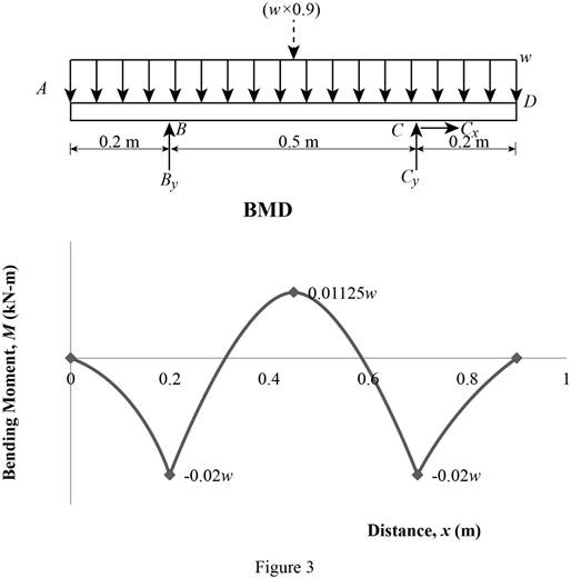
Location of the maximum bending moment:
The maximum bending moment occurs where the shear force changes sign.
Refer to Figure 2;
Use the similar triangle concept.
The maximum bending moment occurs at a distance of 0.45 m from left end of the beam.
Bending moment:
Show the calculation of the bending moment as follows;
Show the calculated bending moment values as in Table 2.
| Location (x) m | Bending moment (M) kN-m |
| A | 0 |
| B | –0.02w |
| Max BM | 0.01125w |
| C | –0.02w |
| D | 0 |
Plot the bending moment diagram as in Figure 3.
Show the free-body diagram of the T-section as in Figure 4.
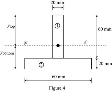
Determine the centroid in y-axis
Here, the area of the section 1 is
Refer to Figure 4;
Substitute
Determine the moment of inertia (I) using the equation.
Here, the depth of the section 1 is
Substitute 60 mm for
Refer to Figure 4;
Tension at Points B and C:
Refer to Figure 3;
Determine the distributed load (w) using the relation.
Substitute –0.02w for
Compression at Points B and C:
Refer to Figure 3;
Determine the distributed load (w) using the relation.
Substitute –0.02w for
Tension at Points E:
Refer to Figure 3;
Determine the distributed load (w) using the relation.
Substitute 0.01125w for
Compression at Points E:
Refer to Figure 3;
Determine the distributed load (w) using the relation.
Substitute 0.01125w for
Refer to the calculated distribution loads; the smallest value controls the design.
Therefore, the largest permissible distributed load (w) is
Want to see more full solutions like this?
Chapter 5 Solutions
Mechanics of Materials-Access (1 Sem. )


- For the wide-flange beam with the loading shown, determine the largest load P that can be applied, knowing that the maximum normal stress is 160 MPa and the largest shearing stress is 100 MPa. W360 x 122 Barrow_forwardKnowing that for the beam shown the allowable stress is 80 MPa in tension and 100 MPa in compression, determine the largest couple M that can be applied. step by step please!!arrow_forwardA fabric used in air-inflated structures is subjected to a biaxial loading that results in normal stresses ox = 18 ksi and oz = 24 ksi.Knowing that the properties of the fabric can be approximated as E = 12.6 x 10 psi and v = 0.34, determine the change in length of (a) side AB, (b) side BC, (c) diagonal AC.arrow_forward
- Straight rods of 0.30-in. diameter and 200-ft length are sometimes used to clear underground conduits of obstructions or to thread wires through a new conduit. The rods are made of high-strength steel and, for storage and transportation, are wrapped on spools of 5-ft diameter. Assuming that the yield strength is not exceeded, determine (a) the maximum stress in a rod, when the rod, which was initially straight, is wrapped on the spool, (b) the corresponding bending moment in the rod. Use E= 29 * 106 psi.arrow_forwardDetermine (a) the distance a for which the maximum absolute value of the bending moment in the beam is as small as possible, (b) the corresponding maximum normal stress due to bending.arrow_forwardFive metal strips, each of 0.5 * 1.5-in. cross section, are bonded together to form the composite beam shown. The modulus of elasticity is 30* 106 psi for the steel, 15 *106 psi for the brass, 10 *106 psi for the aluminum. Knowing that the beam is bent about a horizontal axis by a couple of moment 12 kip·in., determine (a) the maximum stress in each of the three metals, (b) the radius of curvature of the composite beam.arrow_forward
- Knowing that for the beam shown the allowable stress is 12 ksi in ten-sion and 16 ksi in compression, determine the largest couple M that can be applied.arrow_forwardA milling operation was used to remove a portion of a solid bar of square cross section. Knowing that a= 30 mm, d= 20 mm, and σall= 60 MPa, determine the magnitude P of the largest forces that can be safely applied at the centers of the ends of the bar.arrow_forwardA steel pipe and an aluminum pipe are securely bonded together to form the composite beam shown. The modulus of elasticity is 200 GPa for the steel and 70 GPa for the aluminum. Knowing that the composite beam is bent by a couple of moment 500 N?m, determine the maximum stress (a) in the aluminum, (b) in the steel.arrow_forward
- Three wooden planks are fastened together by a series of bolts to form a column. The diameter of each bolt is 12 mm and the inner diameter of each washer is 16 mm, which is slightly larger than the diameter of the holes in the planks. Determine the smallest allowable outer diameter d of the washers, knowing that the average normal stress in the bolts is 36 MPa and that the bearing stress between the washers and the planks must not exceed 8.5 MPa.arrow_forwardDetermine (a) the distance a for which the absolute value of the bending moment in the beam is as small as possible, (b) the corresponding moximum normal stress due to bending.arrow_forwardA weightlifting bar is loaded symmetrically in A and D (P = 1500N of each side). The weightlifter's hands are located at B and C, 0.45 m from A and D. Determine the maximum bending moment in the bar ABCD and the minimum diameter d of the bar knowing that the constraint admissible for the material of the bar is 200MPa.arrow_forward
 Elements Of ElectromagneticsMechanical EngineeringISBN:9780190698614Author:Sadiku, Matthew N. O.Publisher:Oxford University Press
 Mechanics of Materials (10th Edition)Mechanical EngineeringISBN:9780134319650Author:Russell C. HibbelerPublisher:PEARSON
 Thermodynamics: An Engineering ApproachMechanical EngineeringISBN:9781259822674Author:Yunus A. Cengel Dr., Michael A. BolesPublisher:McGraw-Hill Education
 Control Systems EngineeringMechanical EngineeringISBN:9781118170519Author:Norman S. NisePublisher:WILEY
 Mechanics of Materials (MindTap Course List)Mechanical EngineeringISBN:9781337093347Author:Barry J. Goodno, James M. GerePublisher:Cengage Learning
 Engineering Mechanics: StaticsMechanical EngineeringISBN:9781118807330Author:James L. Meriam, L. G. Kraige, J. N. BoltonPublisher:WILEY