
Videos
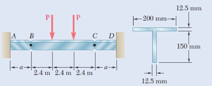
Beams AB, BC, and CD have the cross section shown and are pin-connected at B and C. Knowing that the allowable normal stress is +110 MPa in tension and –150 MPa in compression, determine (a) the largest permissible value of P if beam BC is not to be overstressed, (b) the corresponding maximum distance a for which the cantilever beams AB and CD are not overstressed.
Fig. P5.90
(a)
The largest permissible value of P for the condition that the beam BC is not overstressed.
Answer to Problem 90P
The largest permissible value of P is
Explanation of Solution
Given information:
The allowable normal stress of the material in tension is
The allowable normal stress of the material in compression is
Calculation:
Show the free-body diagram of the section BC as in Figure 1.
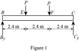
Determine the vertical reaction at point C by taking moment about point B.
Determine the vertical reaction at point B by resolving the vertical component of forces.
Show the free-body diagram of the section AB as in Figure 2.
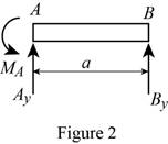
Determine the vertical reaction at point A by resolving the vertical component of forces.
Determine the moment at point A by taking moment about the point A.
Show the free-body diagram of the section CD as in Figure 3.
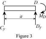
Determine the vertical reaction at point D by resolving the vertical component of forces.
Determine the moment at point D by taking moment about the point D.
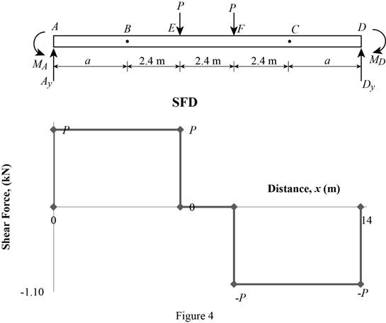
Shear force:
Show the calculation of shear force as follows;
Show the calculated shear force values as in Table 1.
| Location (x) m | Shear force (V) kN |
| A | P |
| E (Left) | P |
| E (Right) | 0 |
| F (Left) | 0 |
| F (Right) | –P |
| D | –P |
Plot the shear force diagram as in Figure 4.
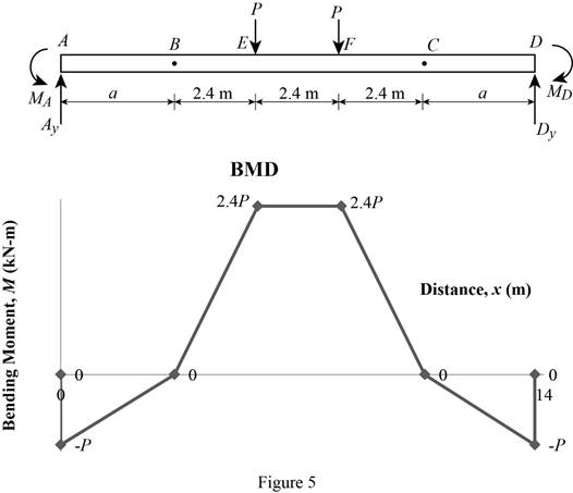
Bending moment:
Show the calculation of the bending moment as follows;
Show the calculated bending moment values as in Table 2.
| Location (x) m | Bending moment (M) kN-m |
| A | Pa |
| B | 0 |
| E | 2.4P |
| F | 2.4P |
| C | 0 |
| D | –Pa |
Plot the bending moment diagram as in Figure 5.
Show the free-body diagram of the T-section as in Figure 6.
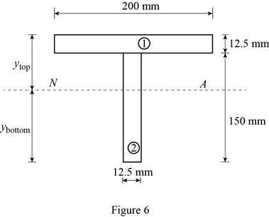
Determine the centroid in y-axis
Here, the area of the section 1 is
Refer to Figure 4;
Substitute
Determine the moment of inertia (I) using the equation.
Here, the depth of the section 1 is
Substitute 12.5 mm for
Refer to Figure 4;
Tension at Points B and D:
Refer to Figure 5;
Determine the moment at points B and D using the relation.
Substitute 110 MPa for
Compression at Points B and C:
Refer to Figure 5;
Determine the moment at points B and D using the relation.
Substitute –150 MPa for
Tension at maximum bending moment:
Refer to Figure 5;
Determine the maximum moment using the relation.
Substitute 110 MPa for
Compression at maximum bending moment:
Refer to Figure 5;
Determine the maximum moment using the relation.
Substitute –150 MPa for
Refer to the calculated distribution loads; the smallest value controls the design.
Refer to Figure 5;
Equate the maximum bending moment calculated and the maximum bending moment in the tension side.
Therefore, the largest permissible value of P for the condition that the beam BC is not overstressed is
(b)
The maximum distance a for the condition that the beams AB and CD are not overstressed.
Answer to Problem 90P
The maximum distance a for the condition that the beams AB and CD are not overstressed is
Explanation of Solution
Refer to Part (a), Figure 4;
The maximum bending moment in the beams AB and CD occurs at the ends A and D.
The calculated maximum bending moment at the points A and D is as follows:
The maximum allowable compression moment at the points A and D is as follows:
Equate the values;
Refer to the answer of the part (a);
Substitute 4.01 kN for P.
Therefore, the maximum distance a for the condition that the beams AB and CD are not overstressed is
Want to see more full solutions like this?
Chapter 5 Solutions
Connect 1-semester Access Card For Mechanics Of Materials - 2016 Update


- For the beam with the cross-section shown, given that: V= 100 N b= 20 cm h=20 cm The max shear stress equals:arrow_forwardThe center span of the Verrazano-Narrows Bridge consists of two uniform roadways suspended from four cables. The design of the bridge allows for the effect of extreme temperature changes that cause the sag of the center span to vary from hw= 386 ft in winter to hs= 394 ft in summer. Knowing that the span is L = 4260 ft, determine the change in length of the cables due to extreme temperature changes.arrow_forwardA weightlifting bar is loaded symmetrically in A and D (P = 1500N of each side). The weightlifter's hands are located at B and C, 0.45 m from A and D. Determine the maximum bending moment in the bar ABCD and the minimum diameter d of the bar knowing that the constraint admissible for the material of the bar is 200MPa.arrow_forward
- Determine (a) the distance a for which the maximum absolute value of the bending moment in the beam is as small as possible, (b) the corresponding maximum normal stress due to bending.arrow_forwardFor the wide-flange beam with the loading shown, determine the largest load P that can be applied, knowing that the maximum normal stress is 160 MPa and the largest shearing stress is 100 MPa. W360 x 122 Barrow_forwardA 12-m simply supported overhang beam is supported at x = 0 and x = 10m. The overhanging portion is from x = 10m to x = 12m (the overhang portion is 2m). Two equal wheel loads of 20kN each, separated by 2m roll as a unit across the 12-m span. Determine the maximum shear developed in the span.arrow_forward
- Two small channel sections DF and EH have been welded to the uniform beam AB of weight W = 3 kN to form the rigid structural member shown. This member is being lifted by two cables attached at D and E . Knowing that 0= 30° and neglecting the weight of the channel sections, (a) draw the shear and bending-moment diagrams for beam AB, (b) determine the maximum absolute values of the shear and bending moment in the beam.arrow_forwardKnowing that the bending moment in the reinforced concrete beam is 1100 kip?ft and that the modulus of elasticity is 3.625 *106 psi for the concrete and 29* 106 psi for the steel, determine (a) the stress in the steel, (b) the maximum stress in the concretearrow_forwardA steel bar and an aluminum bar are bonded together to form the composite beam shown. The modulus of elasticity for aluminum is 70 GPa and for steel is 200 GPa. Knowing that the beam is bent about a horizontal axis by a couple of moment M= 1500 N·m, determine the maximum stress in (a) the aluminum, (b) the steel.arrow_forward
- Determine (a) the distance a for which the absolute value of the bending moment in the beam is as small as possible, (b) the corresponding moximum normal stress due to bending.arrow_forwardDraw the shearing-force and bending-moment diagrams for the following beams: A cantilever of length 20 m carrying a load of 10 kN at a distance of 15 m from the supported end. A cantilever of length 20 m carrying a load of 10 kN uniformly distributed over the inner 15 m of its length. A cantilever of length 12 m carrying a load of 8 kN, applied 5 m from the supported end, and a load of 2kN/m over its whole length.arrow_forwardFor the beam and loading shown, determine the equations of the shear and bending-moment curves and the maximum absolute value of the bending moment in the beam, knowing that (a) k= 1, (b) k= 0.5.arrow_forward
 Elements Of ElectromagneticsMechanical EngineeringISBN:9780190698614Author:Sadiku, Matthew N. O.Publisher:Oxford University Press
 Mechanics of Materials (10th Edition)Mechanical EngineeringISBN:9780134319650Author:Russell C. HibbelerPublisher:PEARSON
 Thermodynamics: An Engineering ApproachMechanical EngineeringISBN:9781259822674Author:Yunus A. Cengel Dr., Michael A. BolesPublisher:McGraw-Hill Education
 Control Systems EngineeringMechanical EngineeringISBN:9781118170519Author:Norman S. NisePublisher:WILEY
 Mechanics of Materials (MindTap Course List)Mechanical EngineeringISBN:9781337093347Author:Barry J. Goodno, James M. GerePublisher:Cengage Learning
 Engineering Mechanics: StaticsMechanical EngineeringISBN:9781118807330Author:James L. Meriam, L. G. Kraige, J. N. BoltonPublisher:WILEY