Videos
The turbocharger of an internal combustion engine consists of a turbine and a compressor. Hot exhaust gases flow through the turbine to produce work, and the work output from the turbine is used as the work input to the compressor. The pressure of ambient air is increased as it flows through the compressor before it enters the engine cylinders. Thus, the purpose of a turbocharger is to increase the pressure of air so that more air gets into the cylinder. Consequently, more fuel can be burned and more power can be produced by the engine.
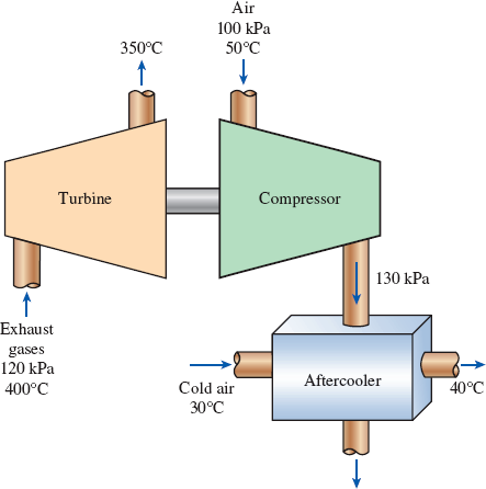
In a turbocharger, exhaust gases enter the turbine at 400°C and 120 kPa at a rate of 0.02 kg/s and leave at 350°C. Air enters the compressor at 50°C and 100 kPa and leaves at 130 kPa at a rate of 0.018 kg/s. The compressor increases the air pressure with a side effect: It also increases the air temperature, which increases the possibility that a gasoline engine will experience an engine knock. To avoid this, an aftercooler is placed after the compressor to cool the warm air with cold ambient air before it enters the engine cylinders. It is estimated that the aftercooler must decrease the air temperature below 80°C if knock is to be avoided. The cold ambient air enters the aftercooler at 30°C and leaves at 40°C. Disregarding any frictional losses in the turbine and the compressor and treating the exhaust gases as air, determine (a) the temperature of the air at the compressor outlet and (b) the minimum volume flow rate of ambient air required to avoid knock.
FIGURE P5–188
(a)
The temperature of the air at the compressor outlet.
Answer to Problem 187RP
The temperature of the air at the compressor outlet is
Explanation of Solution
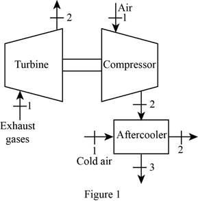
Draw the schematic diagram of the given turbo charger of the engine as shown in
Figure 1.
Write the general energy rate balance equation.
Here, the rate of heat transfer is
The system is at steady state. Hence, the rate of change in net energy of the system becomes zero.
Refer Figure 1 and Refer Equation (I).
For turbine:
Consider the turbine is adiabatic, neglect the heat transfer. Also neglect the kinetic and potential energy changes. The work done is by the system (turbine) and the work done on the system is zero i.e.
The Equations (I) reduced as follows to obtain the work output of compressor.
The change in enthalpy is expressed as follow.
Here, the specific heat of exhaust gas is
Substitute
For compressor:
Consider the compressor is adiabatic, neglect the heat transfer. Also neglect the kinetic and potential energy changes. The work done is on the system (compressor) and the work done by the system is zero i.e.
The Equations (I) reduced as follows to obtain the work input of compressor.
Here, the mass flow rate is
Refer Table A-2(b), “Ideal-gas specific heats of various common gases”.
The specific heat at constant pressure
The specific heat at constant pressure
The specific heat at constant pressure
Conclusion:
Substitute
Here,
Substitute
Thus, the temperature of the air at the compressor outlet is
(b)
The minimum volume flow rate of ambient air required to avoid knock.
Answer to Problem 187RP
The minimum volume flow rate of ambient air required to avoid knock is
Explanation of Solution
Refer Figure 1 and Refer Equation (I).
For aftercooler:
The after cooler is the two inlet and two outlet system.
Refer the Equation (I) Express the energy rate balance equation for aftercooler as follows
Here, subscript
Write the formula for volume flow rate of cold air.
Here, the gas constant of air is
Refer Table A-1, “Molar mass, gas constant, and critical-point properties”.
The gas constant
Conclusion:
Substitute,
Substitute
Thus, the minimum volume flow rate of ambient air required to avoid knock is
Want to see more full solutions like this?
Chapter 5 Solutions
Package: Thermodynamics: An Engineering Approach With 2 Semester Connect Access Card


- The turbines in steam power plants operate essentially under adiabatic conditions. A plant engineer suggests ending this practice. She proposes to run cooling water through the outer surface of the casing to cool the steam as it flows through the turbine. This way, she reasons, the entropy of the steam will decrease, the performance of the turbine will improve, and as a result the work output of the turbine will increase. How would you evaluate this proposal?arrow_forwardSteam flows into a turbine at a rate of 10 kg/s, and 10 kilowatts of heat are lost from the turbine. Ignoring elevation and kinetic energy effects, calculate the power output of the turbine. Inlet conditions are 2.0Mpa and 350oC (h = 3137 kJ/kg) and 0.10Mpa & 100% quality (h = 2675.5 kJ/kg).arrow_forwardA steam power plant receives heat from a furnace at a rate of 280 GJ/h. Heat losses to the surrounding air from the steam as it passes through the pipes and other components are estimated to be about 8 GJ/h. If the waste heat is transferred to the cooling water at a rate of 165 GJ/h, determine net power output.arrow_forward
- Show that the power produced by a wind turbine is proportional to the cube of the wind velocity and to the square of the blade span diameter.arrow_forwardIn a gas turbine , the flow rate of air is 4 kg/sec . The velocity and enthalpy of air at the entrance are 200 m/sec and 6000 KJ/kg respectively . At the exit , the velocity is 100 m/sec and enthlpy is 5000 KJ /kg . A loss of heat of 40 KJ/kg occurs while the air passes through the turbine . Determine the power developed by the turbinearrow_forwardThe mass flow rate of the gas in a gas turbine is 40 kg/s. The specific enthalpy and velocity in the inlet are 1300 kJ/kg and 160 m/s respectively while the outlet are 350 kJ/kg and 50 m/s respectively. Calculate for the work of the turbine if there is a heat loss of 1000 kW. (kW)arrow_forward
- Steam flows into a turbine at the rate of 10 kg/s and 10 kW of heat are lost from the turbine. Ignoring elevation and kinetic energy effects, calculate the power output from the turbine.Note : h1 = 2739 kJ /kg and h2 = 2300.5 kJ / kg CHOICES: A. 4605 kW B. 4973 kW C. 4375 kW D. 4000 kWarrow_forwardAir at 7°C enters a turbojet engine at a rate of 16 kg/s and at a velocity of 220 m/s (relative to the engine). Air is heated in the combustion chamber at a rate 15,000 kJ/s, and it leaves the engine at 427°C. Determine the thrust produced by this turbojet engine. (Hint: Choose the entire engine as your control volume.)arrow_forwardThe shaft power from a 90 percent-efficient turbine is 500 kW. If the mass flow rate through the turbine is 440 kg/s, the extracted head removed from the fluid by the turbine is (a) 44.0 m (b) 49.5 (c) 142 m (d ) 129 m (e) 98.5 marrow_forward
- 1.) A water jet that leaves a nozzle at 58.08 m/s at a flow rate of 118.14 kg/s is to be used to generate power by striking the buckets located on the perimeter of a wheel. Determine the power generation (kW) potential of this water jet. 2.)A man weighing 91.93 lbf is pushing a cart that weighs 174.93 lbf with its contents up a ramp that is inclined at an angle of 9.06o from the horizontal. Determine the work needed to move along this ramp a distance of 93.79 ft considering the man as the system. Express your in Btu.arrow_forwardWater vapor enters the steam turbine at 4000 kPa pressure, 500 ° C temperature and 6 m 3 / s volume flow , as shown in the figure below . 0.2 times the mass flow rate of the incoming water from outlet no.2 with 500 kPa pressure and 200 ° C temperature, 0.8 times the mass flow of water, exit no 3 with 30 kPa pressure and 0.85 dryness degree. Since the heat transfer from the turbine to the environment is 5000 kW,(Changes in kinetic and potential energies are negligible) find the mass flow of the incoming water . Find the volume flow of water at outlet no. 3 Find the power (kW) produced by the turbine.arrow_forwardAn adiabatic pump is used to increase the pressure of water from 100 kPa to 500 kPa at a rate of 400 L/min. If the efficiency of the pump is 75 percent, the maximum temperature rise of the water across the pump is (a) 0.096° C (b) 0.058° C (c) 0.035° C (d ) 1.52° C (e) 1.27° Carrow_forward
 Elements Of ElectromagneticsMechanical EngineeringISBN:9780190698614Author:Sadiku, Matthew N. O.Publisher:Oxford University Press
 Mechanics of Materials (10th Edition)Mechanical EngineeringISBN:9780134319650Author:Russell C. HibbelerPublisher:PEARSON
 Thermodynamics: An Engineering ApproachMechanical EngineeringISBN:9781259822674Author:Yunus A. Cengel Dr., Michael A. BolesPublisher:McGraw-Hill Education
 Control Systems EngineeringMechanical EngineeringISBN:9781118170519Author:Norman S. NisePublisher:WILEY
 Mechanics of Materials (MindTap Course List)Mechanical EngineeringISBN:9781337093347Author:Barry J. Goodno, James M. GerePublisher:Cengage Learning
 Engineering Mechanics: StaticsMechanical EngineeringISBN:9781118807330Author:James L. Meriam, L. G. Kraige, J. N. BoltonPublisher:WILEY