
Laboratory Manual for Introductory Circuit Analysis
13th Edition
ISBN: 9780133923780
Author: Robert L. Boylestad, Gabriel Kousourou
Publisher: PEARSON
expand_more
expand_more
format_list_bulleted
Concept explainers
Videos
Textbook Question
Chapter 6, Problem 15P
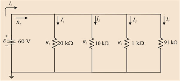
For the parallel network in Fig. 6.78:
- Without making a single calculation, make a guess on the total resistance.
- Calculate the total resistance, and compare it to your guess in part (a).
- Without making a single calculation, which branch will have the most current? Which will have the least?
- Calculate the current through each branch, and compare your results to the assumptions of part (c).
- Find the source current and test whether it equals the sum of the branch currents.
- How does the magnitude of the source current compare to that of the branch currents?
Expert Solution & Answer
Want to see the full answer?
Check out a sample textbook solution
Students have asked these similar questions
Assume there are 10 light bulbs that can be connected in series and 10 light bulbs that can be connected in parallel. Each bulb is rated 40 W. If the voltage at the plug is 220 V for both series and parallel connections, calculate the current through each bulb for both cases. Also find the voltage across each bulb.
13)This multiple choice question from MEASUREMENTS INSTRUMENTATIONS course.
Give me right solution with clear calculations
Chapter 6 Solutions
Laboratory Manual for Introductory Circuit Analysis
Ch. 6 - For each configuration in Fig. 6.64, find the...Ch. 6 - For each configuration of Fig. 6.65, �nd the...Ch. 6 - For the network in Fig. 6.66: Find the elements...Ch. 6 - Find the total resistance for each configuration...Ch. 6 - Find the total resistance for each configuration...Ch. 6 - For each circuit board in Fig. 6.69, �nd the...Ch. 6 - The total resistance of each of the configurations...Ch. 6 - The total resistance for each configuration of...Ch. 6 - For the parallel network in Fig. 6.72, composed of...Ch. 6 - What is the ohmmeter reading for each...
Ch. 6 - Determine R1 for the network in Fig. 6.749.Ch. 6 - For the parallel network in Fig. 6.75: Find the...Ch. 6 - For the network of Fig. 6.76: Find the current...Ch. 6 - Repeat the analysis of Problem 13 for the network...Ch. 6 - For the parallel network in Fig. 6.78: Without...Ch. 6 - Given the information provided in Fig. 6.79, find:...Ch. 6 - Use the information in Fig. 6.80, to calculate:...Ch. 6 - Given the information provided in Fig. 6.81, find...Ch. 6 - For the network of Fig. 6.82, find: The voltage V....Ch. 6 - Using the information provided in Fig. 6.83 find:...Ch. 6 - For the network in Fig. 6.77: Redraw the network...Ch. 6 - For the configuration in Fig. 6.84: Find the total...Ch. 6 - Eight holiday lights are connected in parallel as...Ch. 6 - Determine the power delivered by the dc battery in...Ch. 6 - A portion of a residential service to a home is...Ch. 6 - For the network in Fig. 6.88: Find the current l1....Ch. 6 - Using Kirchhoffs current law, determine the...Ch. 6 - Using Kirchoffs current law, find the unknown...Ch. 6 - Using Kirchhoffs current law, determine the...Ch. 6 - Using the information provided in Fig. 6.92, find...Ch. 6 - Find the unknown quantities for the networks in...Ch. 6 - Find the unknown quantities for the networks of...Ch. 6 - Based solely on the resistor values, determine all...Ch. 6 - Determine one of the unknown currents of Fig....Ch. 6 - For each network of Fig. 6.97, determine the...Ch. 6 - Parts (a) through (e) of this problem should be...Ch. 6 - Find the unknown quantities for the networks in...Ch. 6 - Find resistance R for the network in Fig. 6.100...Ch. 6 - Design the network in Fig. 6.101 such that I2=2I1...Ch. 6 - Assuming identical supplies in Fig. 6.102: Find...Ch. 6 - Assuming identical supplies, determine currents...Ch. 6 - Assuming identical supplies, determine the current...Ch. 6 - For the simple series con�guration in Fig....Ch. 6 - Given the configuration in Fig. 6.106: What is the...Ch. 6 - Based on the measurements of Fig. 6.107, determine...Ch. 6 - Referring to Fig. 6.108, find the voltage Vab...Ch. 6 - The voltage Va for the network in Fig. 6.109, is...Ch. 6 - Prob. 48PCh. 6 - Using PSpice or Multisim, determine the solution...Ch. 6 - Using PSpice or Multisim, determine the solution...
Additional Engineering Textbook Solutions
Find more solutions based on key concepts
The current source in the circuit shown generates the current pulse
Find (a) v (0); (b) the instant of time gr...
Electric Circuits. (11th Edition)
With respect to the circuit in Fig. 5.90, (a) employ Thévenin’s theorem to determine the equivalent network see...
Loose Leaf for Engineering Circuit Analysis Format: Loose-leaf
For the “tank” circuit in Fig. 14.79, find the resonant frequency.
Figure 14.79
For Probs. 14.39, 14.71, and 1...
Fundamentals of Electric Circuits
Does the severity of an electric shock increase ordecrease with eh of the following changes? a. A decrease in t...
Electric Motors and Control Systems
The voltage source of the circuit shown in Fig. P1.29 is given by s(t)=25cos(4104t45)(V). Obtain an expression ...
Fundamentals of Applied Electromagnetics (7th Edition)
How many coulombs do 93.8 1016 electrons represent?
Principles Of Electric Circuits
Knowledge Booster


Learn more about
Need a deep-dive on the concept behind this application? Look no further. Learn more about this topic, electrical-engineering and related others by exploring similar questions and additional content below.Similar questions
- 1. Design a problem, complete with solution. Use at least three resistors and one voltage source. You may use the 3 resistors in any way you wish so long as the concepts of Ohm's Law, Series and Parallel Circuits are discussed.arrow_forwardGive 5 example of parallel circuit found in homearrow_forwardexample (H.w): A Current has an internal resistance of 782 ed to measure the Current through Rc in the below is used creuit. Find the percentuge error of the reading due to Ammeter hocaeding. Razike Rbzikuz AAmmeterarrow_forward
- 1. a) Design a combination circuit that has four LED’s and one resistor. Each LED will be in parallel and have its own switch. The circuit will have a resistor in series with the LED’s while they are connected in parallel. Each LED’s will drop 1.4vDC in parallel, with the same specifications. Make sure you size R1 (resistor R1) correctly using a VT of 9v. Each LED branch will have 20mA of current through it. Calculate all values including power at each component. b) Also, if the 9v battery had a rating of 2 watt-hours, how long would it last? If you wanted to make each LED 1/3 brighter than the other in parallel, how would you change the circuit to make that happen? Explain and show calculations. (Hint… you do not need transistor(s), but you can use them in your design).arrow_forwardCurrent sources in parallel Select one: a. When two or more voltage sources are connected in series, the total voltage equals to the sum of all individual voltage sources b. When two or more current sources are connected in series, the total current equals to the sum of all individual current sources c. None of the answers d. When two or more current sources are connected in parallel, the total current equals to the sum of all individual current sources e. When two or more voltage sources are connected in parallel, the total current equals to the sum of all individual current sourcesarrow_forwardResistors are said to be connected in series when.circuit elements carry the same current. Select one True Falsearrow_forward
- Norton Theorem states that an entire network connected to a pair of terminals can be replaced with A. a single voltage source in parallel with single resistance B. a single current source in parallel with a single resistance C. a single voltage source in series with a single resistance D. a single current source in series with a single resistancearrow_forwardB 12 V (+ 32 kn I, A 1 kM 2 kN 1 kN 2 mA Darrow_forwardUsing the rules for parallel circuits and Ohmslaw, solve for the missing values. ETE1E2E3E4ITl1I2l33.2AI4RT3.582R116R210R3R420PTP1P2P3P4arrow_forward
- 20/ Many resistors connected in parallel will divide the voltage proportionally among all the resistors. Select one: True Falsearrow_forwardAssume you have a 6V battery and a 1.5V flashlight bulb which draws 0.5A when the bulb voltage is 1.5V. Design a network of resistors to go between the battery and the bulb to give VS=1.5V when the bulb is connected yet ensures that VS does not rise above 2V when the bulb is disconnected.arrow_forwarda) Two or more resistors in a circuit are said to be in parallel when all the resistors are connected to the same nodes and the same voltage is appearing across all these elements. Two or more resistors in a circuit are also said to be in series when the current flowing through all the resistors is the same. With the aid of three resistors,4Ohm’s law and diagrams derive the two important total resistance formulas for the two connections to verify these two postulates b) Using your formulations in (a), find the current in the Load Resistor RL of resistance 30Ω and Thevenin’s resistance Rth of Figure 4 below. c) Find the resistance Req shown in the circuit in Figure 4 below using your knowledge of parallel and series connections demonstrated in (a)arrow_forward
arrow_back_ios
SEE MORE QUESTIONS
arrow_forward_ios
Recommended textbooks for you
 Delmar's Standard Textbook Of ElectricityElectrical EngineeringISBN:9781337900348Author:Stephen L. HermanPublisher:Cengage Learning
Delmar's Standard Textbook Of Electricity
Electrical Engineering
ISBN:9781337900348
Author:Stephen L. Herman
Publisher:Cengage Learning
Kirchhoff's Rules of Electrical Circuits; Author: Flipping Physics;https://www.youtube.com/watch?v=d0O-KUKP4nM;License: Standard YouTube License, CC-BY