
Concept explainers
Videos
Plot the following graphs for the pressure varies from
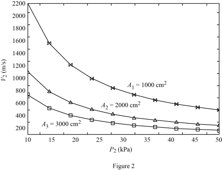
- Exit velocity versus exit pressure power output of turbine
- Turbine power output versus exit pressure power output of turbine
Explanation of Solution
The turbine operates steadily. Hence, the inlet and exit mass flow rates are equal.
Write the formula for inlet mass flow rate.
Here, the cross-sectional area is
At inlet:
The steam is at the state of superheated condition.
Refer Table A-6, “Superheated water”.
Obtain the inlet enthalpy
The turbine operates steadily. Hence, the inlet and exit mass flow rates are equal.
Write the formula for exit mass flow rate.
Here, the cross-sectional area is
Rearrange the Equation (II) to obtain exit velocity
At exit:
Consider the exit pressure
The steam is with the quality of
Write the formula for exit enthalpy
Write the formula for exit specific volume
Here, the enthalpy is
Refer Table A-5, “Saturated water—Pressure table”.
Obtain the following corresponding to the pressure of
Consider the steam flows at steady state. Hence, the inlet and exit mass flow rates are equal.
Write the energy rate balance equation for one inlet and one outlet system.
Here, the rate of heat transfer is
The steam flows at steady state through the turbine. Hence, the rate of change in net energy of the system becomes zero.
Heat loss occurs at the rate of
The Equations (VI) reduced as follows to obtain the work output
Here,
Rewrite the Equation (VII) as follows.
Calculation:
Substitute
Substitute
Equation (V).
Substitute
Consider the exit area
Substitute
Equation (III).
Substitute
The exit velocity
Using excel spread sheet, the exit velocity
| S.No. | |||
| 1 | 10 | 2253.540216 | –22171.1196 |
| 2 | 15 | 1539.230498 | –514.857057 |
| 3 | 20 | 1174.871104 | 7295.806083 |
| 4 | 25 | 952.9435377 | 10965.91684 |
| 5 | 30 | 803.2150134 | 12968.62817 |
| 6 | 40 | 613.4390747 | 14943.44488 |
| 7 | 50 | 497.7670121 | 15822.49054 |
Table 1
Similarly, the exit velocity
| S.No. | |||
| 1 | 10 | 1126.770108 | 8623.292217 |
| 2 | 15 | 769.6152491 | 13851.56455 |
| 3 | 20 | 587.435552 | 15665.73428 |
| 4 | 25 | 476.4717689 | 16472.41662 |
| 5 | 30 | 401.6075067 | 16880.6829 |
| 6 | 40 | 306.7195374 | 17225.27947 |
| 7 | 50 | 248.883506 | 17324.918 |
Table 2
Similarly, the exit velocity
| S.No. | |||
| 1 | 10 | 751.180072 | 14325.96107 |
| 2 | 15 | 513.0768327 | 16512.01299 |
| 3 | 20 | 391.6237013 | 17215.72099 |
| 4 | 25 | 317.6478459 | 17492.1388 |
| 5 | 30 | 267.7383378 | 17605.13749 |
| 6 | 40 | 204.4796916 | 17647.84143 |
| 7 | 50 | 165.9223374 | 17603.1453 |
Table 3
Refer Table 1, 2, and 3.
Plot the graph for the exit pressure
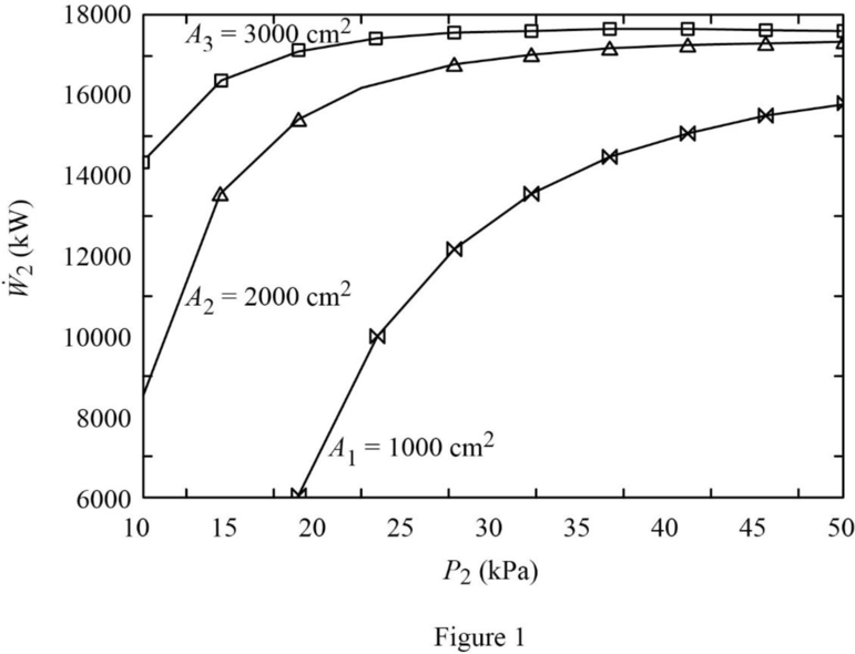
Refer Table 1, 2, and 3.
Plot the graph for the exit pressure
Want to see more full solutions like this?
Chapter 6 Solutions
Fundamentals Of Thermal-fluid Sciences In Si Units


 Elements Of ElectromagneticsMechanical EngineeringISBN:9780190698614Author:Sadiku, Matthew N. O.Publisher:Oxford University Press
 Mechanics of Materials (10th Edition)Mechanical EngineeringISBN:9780134319650Author:Russell C. HibbelerPublisher:PEARSON
 Thermodynamics: An Engineering ApproachMechanical EngineeringISBN:9781259822674Author:Yunus A. Cengel Dr., Michael A. BolesPublisher:McGraw-Hill Education
 Control Systems EngineeringMechanical EngineeringISBN:9781118170519Author:Norman S. NisePublisher:WILEY
 Mechanics of Materials (MindTap Course List)Mechanical EngineeringISBN:9781337093347Author:Barry J. Goodno, James M. GerePublisher:Cengage Learning
 Engineering Mechanics: StaticsMechanical EngineeringISBN:9781118807330Author:James L. Meriam, L. G. Kraige, J. N. BoltonPublisher:WILEY