Videos
Determine the force in each member of the truss. State if the members are in tension or compression.
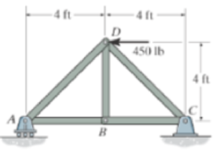
Prob. F6-1
The force in each member of truss and the state of members are in tension or compression.
Answer to Problem 1FP
The magnitudes and the state of members are as follows:
- The magnitude of force in the member AD is
- The magnitude of force in the member AB is
- The magnitude of force in the member BD is
- The magnitude of force in the member BC is
- The magnitude of force in the member CD is
Explanation of Solution
Method adopted:Method of Joints
Assumptions:
- Consider the state of member as tension where the force is pulling the member and as compression where the force is pushing the member.
- Consider the force indicating right side as positive and left side as negative in horizontal components of forces.
- Consider the force indicating upside is taken as positive and downside as negative in vertical components of forces.
- Consider clockwise moment as positive and anti-clock wise moment as negative wherever applicable.
Find the reactions.
Show the free body diagram of truss as in Figure (1).
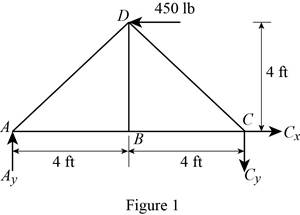
Using Figure (1),
Take moment at joint A and equate to zero.
Along the vertical direction:
Determine the reaction at joint A by resolving the vertical component of forces.
Substitute 225 lb for
Along the horizontal direction:
Determine the horizontal reaction
Joint A:
Show the free body diagram of the Joint A in Figure (2).
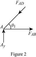
Using Figure (2),
Determine the value of
Substitute 4 ft for opposite side and 4 ft for adjacent side in Equation (I).
Along the vertical direction:
Determine the force in the member AD by resolving the vertical component of forces.
Along the horizontal direction:
Determine the force in the member AB by resolving the horizontal component of force.
Show the calculation of force in the members as follows:
Conclusion:
Substitute 225 lb for
Thus, the magnitude of force in the member AD is
Substitute 318.20 lb for
Thus, the magnitude of force in the member AB is
Joint B:
Show the free body diagram of the Joint B in Figure (3).
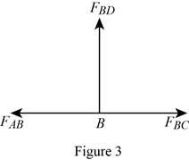
Using Figure (3),
Along the vertical direction:
Determine the force in the member BD by resolving the vertical component of force.
Along the horizontal direction:
Determine the force in the member BC by resolving the horizontal component of force.
Show the calculation of force in the members as follows:
Conclusion:
Refer to Equation (IV).
There is no vertical force acting in the member BD. Therefore the force in the member
Thus, the magnitude of force in the member BD is
Substitute 225 lb for
Thus, the magnitude of force in the member BC is
Joint C:
Show the free body diagram of the Joint C in Figure (4).
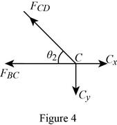
Using Figure (4),
Substitute 4 ft for opposite side and 4 ft for adjacent side in Equation (I).
Along the vertical direction:
Determine the force in the member CD by resolving the vertical component of forces.
Show the calculation of forces in the members as follows:
Conclusion:
Substitute 225 lb for
Thus, the magnitude of force in the member CD is
Want to see more full solutions like this?
Chapter 6 Solutions
ENGR.MECH.:STAT.+DYNAMICS


- Determine the forces in members BJ, BI, CI, CH, DG, DH, and EG of the loaded truss. All triangles are 45°-45°-90°. The forces are positive if in tension, negative if in compression.arrow_forwardUsing the attached image, determine the force in each member of the truss and state if the members are in tension or compression. Set P1= 2 kN and P2= 1.5 kN. Use method of joint.arrow_forwardFind the force in member AB of the truss and indicate whether it is in Tension or Compression, given: F = 35 lbs, θ = 46 °arrow_forward
- Determine the force in each member of the truss and state if the members are in tension or compression. Set P1=2 kN and P2=1.5 kN.arrow_forwardDetermine the froce in each member of the truss. Assume the diagonals cannot support a compressive forcearrow_forwardDetermine the force in member BE. State whether the member is in tension or compression. Set P = 10 kN.arrow_forward
- Determine the force in each member of the truss, and state if the members are in tension or compression. Hint: The horizontal force component at A must be zero. Why?arrow_forwardUsing Method Of Sections, Determine The Forces In Members CD And DF. 5 KN 4 KN 3 KN 2 KN |-3 M +-3m-+-3 M+-3m- 3.arrow_forwardDetermine the force in each member of the loaded truss. The forces are positive if in tension, negative if in compression. Assume F1 = 3600 lb, F2 = 3200 lb, a=4.1 ft, b=6.6 ft, c=2.2 ft, d=3.2 ftarrow_forward
- Determine the force in members FG, FH, and HG of the truss which serves to support the deck of a bridge if P1 = 50kN, P2 = 20kN and P3 = 10kN. State if these members are in tension or compression.arrow_forwardDetermine the forces on the DF, EF and EG members, indicating whether they are traction or compression. Use the section method.H = 83arrow_forwardDetermine the force in member 2 of the assembly as shown if the support at joint 1 settles downward 25 mm. Take AE = 8(103) kN.arrow_forward
 Elements Of ElectromagneticsMechanical EngineeringISBN:9780190698614Author:Sadiku, Matthew N. O.Publisher:Oxford University Press
 Mechanics of Materials (10th Edition)Mechanical EngineeringISBN:9780134319650Author:Russell C. HibbelerPublisher:PEARSON
 Thermodynamics: An Engineering ApproachMechanical EngineeringISBN:9781259822674Author:Yunus A. Cengel Dr., Michael A. BolesPublisher:McGraw-Hill Education
 Control Systems EngineeringMechanical EngineeringISBN:9781118170519Author:Norman S. NisePublisher:WILEY
 Mechanics of Materials (MindTap Course List)Mechanical EngineeringISBN:9781337093347Author:Barry J. Goodno, James M. GerePublisher:Cengage Learning
 Engineering Mechanics: StaticsMechanical EngineeringISBN:9781118807330Author:James L. Meriam, L. G. Kraige, J. N. BoltonPublisher:WILEY