
Concept explainers
Videos
Determine the shape factor for the wide-flange beam.
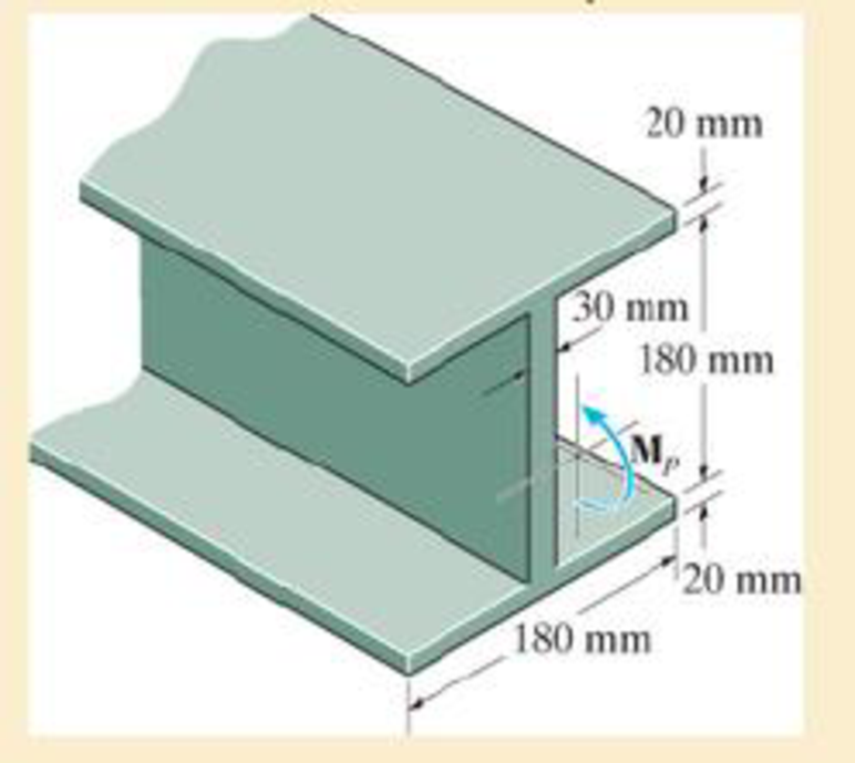
R6–1
Answer to Problem 1RP
The shape factor for the wide-flange beam is
Explanation of Solution
Determination of Elastic moment:
Moment of inertia:
Show the free-body diagram of the beam as in Figure 1.
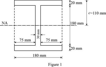
Consider the beam as rectangular and determine the moment of inertia for rectangular section and deduct the moment of inertia of the two smaller rectangular portions.
Determine the moment of inertia of the I-section using the formula.
Here, B is width of rectangular section, D is depth of large rectangular section, b is depth of small rectangular section, and d is depth of small rectangular section.
Substitute 180 mm for B, 220 mm for D, 75 mm for b, and 180 mm for d in Equation (1).
Elastic moment:
Determine the elastic moment using the equation.
Here,
Substitute
Determination of plastic moment:
Show the free-body diagram of the profile view of the I-beam as in Figure 2.
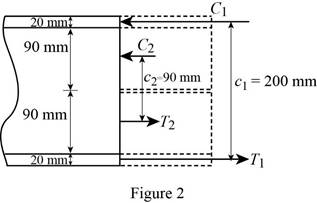
Determine the plastic moment in the I-section using the equation.
Here,
Substitute 180 mm for
Shape factor:
Determine the shape factor for the I-section using the formula.
Substitute
Thus, the shape factor for the wide-flange beam is
Want to see more full solutions like this?
Chapter 6 Solutions
MECHANICS OF MATERIALS


- Determine the shear stress (in Mpa) in the 28.54-mm-diameter pin at B that support the beam if P = 35.79 kN, a = 2.76 m, and b = 5.95 m.arrow_forwardQ: Determine the internal normal force and shear F kip force, and the bending moment in the beam at point D. Assume the support at B is a roller. 40 kip-ft Section A: Take F = 10 kip Section B: Take F = 4 kip D B 8 ft 8 ft 8 ftarrow_forwardQ1/ A composite beam is made of wood and reinforced with steel strap located on its bottom side. It has the cross-sectional area shown in fig. if the beam is subjected to a bending moment of M=2kN.m, determine the normal stress at wood and steel. Take Ew=12Gpa and Est=200Gpa. 150mm Wood en 20mm Steel 150mmarrow_forward
- If the beam is made from a material having an allowable tensile and compressive stress of (Callow), = 125 MPa and (Callow)c = 150 MPa, respectively, determine the maximum allowable internal moment M that can be applied to the beam.arrow_forwardDetermine the minimum width of the beam to the nearest 1/4 in. that will safely support the loading of P = 8 kip. The allowable bending stress is sallow = 24 ksi and the allowable shear stress is tallow = 15 ksi.arrow_forwardThe Douglas Fir beam is reinforced with A-36 steel straps at its sides. Determine the maximum stress in the wood and steel if the beam is subjected to a bending moment of Mz = 4 kN # m. Sketch the stress distribution acting over the cross section.arrow_forward
- the 1m beam shown is subjected to 6 kN. if the beams has a rectangular cross section as shown where b = 0.2 m h = 0.5 m the maximum bending stress on the beam at section a-a when d = 0.3 m is kPa aarrow_forward20 mm 20 mm 4. The simply supported beam on the right is built up from three boards by nailing them together as shown. If P = 12 kN, determine the maximum allowable spacing s of the nails to support the load, if each nail can resist a shear force of 1.5 kN. 1 m m B 100 mm 25 mm- 25 mm 200 mm 25 mmarrow_forwardThe simply supported joist is used in the construction of a floor for a building. In order to keep the floor low with respect to the sill beams C and D, the ends of the joist are notched as shown. If the allowable shear stress is tallow = 350 psi and the allowable bending stress is s allow = 1700 psi, determine the smallest height h so that the beam will support a load of P = 600 lb. Also, will the entire joist safely support the load? Neglect the stress concentration at the notch.arrow_forward
- Determine the bending stress at corners A and B. What is the orientation of the neutral axis?arrow_forwardThe beam is supported by a pin at point A and a roller at kN point B. A distributed load of W₁ = 8 - and an applied m force of F₁ = 12 kN are applied to the beam. The beam has an allowable bending stress of allow = 6 MPa. Neglect the weight and thickness of the beam. Take the origin for all functions to be at A., i.e. start at the left and go right. Must use positive sign convention for V and M. d3 1 d3 d1 W1 d1 B O h d2 F₁ Values for the figure are given in the following table. Note the figure may not be to scale. Dimensions for the whole beam Variable Value d₁ 4 m d₂ 2 marrow_forwardIf the beam in Prob. 6–28 has a rectangular cross section with a width b and a height h, determine the absolute maximum bending stress in the beam.arrow_forward
 Elements Of ElectromagneticsMechanical EngineeringISBN:9780190698614Author:Sadiku, Matthew N. O.Publisher:Oxford University Press
 Mechanics of Materials (10th Edition)Mechanical EngineeringISBN:9780134319650Author:Russell C. HibbelerPublisher:PEARSON
 Thermodynamics: An Engineering ApproachMechanical EngineeringISBN:9781259822674Author:Yunus A. Cengel Dr., Michael A. BolesPublisher:McGraw-Hill Education
 Control Systems EngineeringMechanical EngineeringISBN:9781118170519Author:Norman S. NisePublisher:WILEY
 Mechanics of Materials (MindTap Course List)Mechanical EngineeringISBN:9781337093347Author:Barry J. Goodno, James M. GerePublisher:Cengage Learning
 Engineering Mechanics: StaticsMechanical EngineeringISBN:9781118807330Author:James L. Meriam, L. G. Kraige, J. N. BoltonPublisher:WILEY