
Videos
(a)
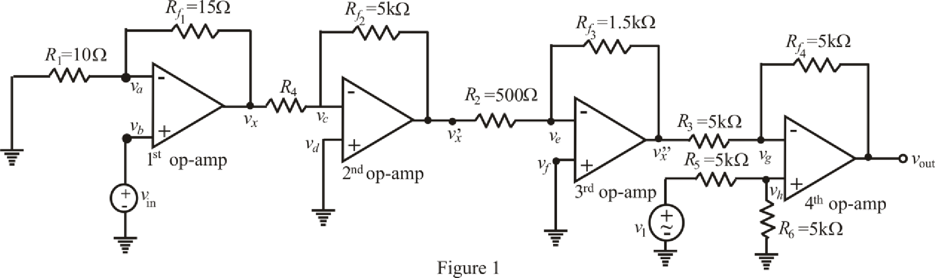
Find the output voltage of the circuit.
(a)
Answer to Problem 24E
The output voltage of combined circuit is
Explanation of Solution
Given data:
Combine the two circuits by eliminating the
Connect the output of circuit shown in FIGURE 6.49 to left-hand terminal of
Value of resistance
Value of input voltage of 1st op amp
Value of input voltage of 4th op amp
Calculation:
The redrawn circuit from given data is shown in Figure 1 as follows.
The expression for nodal analysis at node voltage
Here,
The expression for the virtual ground concept across 1st op amp is as follows.
Substitute
Rearrange for
Rearrange for
Substitute
Substitute
The expression for the nodal analysis at node voltage
Here,
The expression for the virtual ground concept across 2nd op amp is as follows,
Substitute
Rearrange for
Substitute
The expression for the nodal analysis at node voltage
Here,
The expression for the virtual ground concept across 3rd op amp is as follows.
Substitute
Rearrange for
Substitute
The expression for the nodal analysis at node voltage
Here,
The expression for the nodal analysis at node voltage
Here,
The expression for the virtual ground concept across 3rd op amp is as follows,
Simplify equation (14) for
Rearrange for
Substitute
Rearrange for
Rearrange for
Substitute
Solve for
Conclusion:
Thus, the output voltage of combined circuit is
(b)
Find the output voltage of the circuit.
(b)
Answer to Problem 24E
The output voltage of combined circuit is
Explanation of Solution
Given Data:
Value of resistance
Value of input voltage of 1st op amp
Value of input voltage of 4th op amp
Calculation:
Refer to the Figure 1,
Substitute
Substitute
Substitute
Substitute
Solve for
Conclusion:
Thus, the output voltage of combined circuit is
(c)
Find the output voltage of the circuit.
(c)
Answer to Problem 24E
The output voltage of combined circuit is
Explanation of Solution
Given Data:
Value of resistance
Value of input voltage of 1st op amp
Value of input voltage of 4th op amp
Calculation:
Refer to the Figure 1,
Substitute
Substitute
Substitute
Substitute
Solve for
Conclusion:
Thus, the output voltage of combined circuit is
Want to see more full solutions like this?
Chapter 6 Solutions
ENGINEERING CIRCUIT ANALYSIS ACCESS >I<


- A 100-pF capacitor is constructed of parallel plates of metal, each having a width W anda length L. The plates are separated by air with a distance d. Assume that L and W are bothmuch larger than d. What is the new capacitance ifa. both L and W are doubled and the other parameters are unchanged?b. the separation d is doubled and the other parameters are unchanged from their initialvalues? c. the air dielectric is replaced with oil having a relative dielectric constant of 25 and theother parameters are unchanged from their initial values ?arrow_forwardTwo capacitors with 2.0 F and 3.0 F capacitance, respectively, are connected in parallel and subjected to total potential difference of 100 V. Find the (a) total capacitance, (b) charge stored in each capacitor, and (c) potential difference across each capacitor.arrow_forwardA mesh collider a) is as accurate as the triangle count on the mesh b)is the variable optiom for complex meshes such as player characters c)is the only way to get headshots to work d)is faster than a box colliderarrow_forward
- 1. Calculate the capacitance between two parallel plates, each of which is 100 sq. Inches and 2 mm apart in air. 2. A capacitor is charged with 0.23 J of energy at a voltage of 48V. What is its capacitance? 3. A 50-uF capacitor is initially charged. Determine the initial charge of the 50-uF capacitor if the charge transferred to a 100-uF capacitor, when connected in parallel, is 200-uC.arrow_forward6 A capacitor is constructed with parallel metal plates, If the plate separation is 2 mm and the capacitance is given to 1 nano Farads, determine the area of the parallel plates of the device. Select one: a. 0.12 square meters b. 0.23 square meters c. 0.27 square meters d. 0.20 square metersarrow_forwardDesign a circuit that amplifies a 500 mV signal originating from a computer keyboard, so that this signal can be interpreted by the digital circuits found on the motherboard.arrow_forward
- In a city in England with a temperature of 18 ° C, it is desired to install a wind farm with 10 wind turbines 80m high and aerodynamic coefficient equal to 0.3. For this, a study of wind measurement through an anemometer installed at 15 m height indicating speed 5 m / s in a place with high grass. Size the turbine blades in this wind farm so that obtain a mechanical power of 500 kW that will supply the entire community, calculating the diameter of the rotor blades.arrow_forward1. A 2.0 Ω resistor is connected to a non-ideal source with internal resistance equal to 1.0 Ω and EMF equal to 15V. If the potential measured by the voltmeter across the resistor is 10V, find the rate of electrical energy dissipation in the battery.arrow_forward1. Theoretically calculate the voltage across the capacitor in the circuit of Figure 1 when t = 0 s, 5 s, 10 s, 20 s, 30 s, 40 s, and 60 s, assuming that the circuit is under DC conditions when t < 0 s and the switch is opened at t = 0 s. 2. Compare the calculated voltage at t = 20 s with the experimentally measured ∆?.arrow_forward
- Please assist with this Matlab exercise. Image exercise 2arrow_forwardDefibrillator machines are used to deliver an electric shock to the human heart, to resuscitate a heart that has stopped beating. It is estimated that a current as low as 18 mA through the heart is required to resuscitate. Using 95 kN as the resistance, determine the output voltage a defibrillator needs.arrow_forwardTwo coils of inductances 4 H and 6 H are connected in parallel. If their mutual inductance is 3 H. Calculate the equivalent inductance of the combination if mutual inductance assists and if mutual inductance opposes the self-inductance respectively.arrow_forward
 Introductory Circuit Analysis (13th Edition)Electrical EngineeringISBN:9780133923605Author:Robert L. BoylestadPublisher:PEARSON
 Delmar's Standard Textbook Of ElectricityElectrical EngineeringISBN:9781337900348Author:Stephen L. HermanPublisher:Cengage Learning
 Programmable Logic ControllersElectrical EngineeringISBN:9780073373843Author:Frank D. PetruzellaPublisher:McGraw-Hill Education
 Fundamentals of Electric CircuitsElectrical EngineeringISBN:9780078028229Author:Charles K Alexander, Matthew SadikuPublisher:McGraw-Hill Education
 Electric Circuits. (11th Edition)Electrical EngineeringISBN:9780134746968Author:James W. Nilsson, Susan RiedelPublisher:PEARSON
 Engineering ElectromagneticsElectrical EngineeringISBN:9780078028151Author:Hayt, William H. (william Hart), Jr, BUCK, John A.Publisher:Mcgraw-hill Education,