
Concept explainers
Videos
Derive the expression for
Answer to Problem 55E
The derived expression for
Explanation of Solution
Calculation:
The redrawn circuit is shown in Figure 1 as follows.
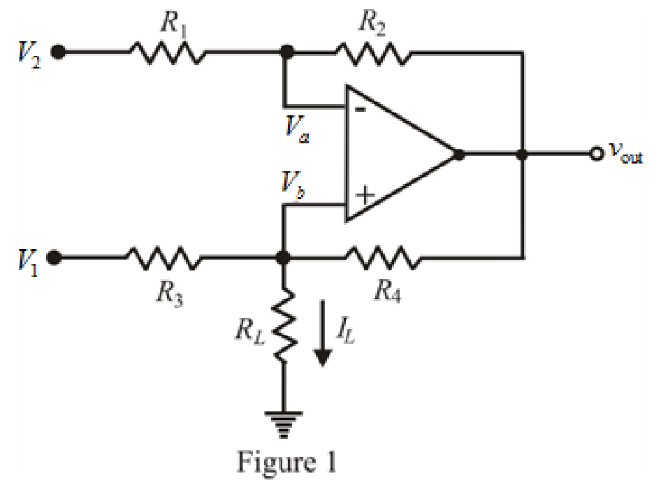
Refer to the Figure 1.
The expression for nodal analysis at node voltage
Here,
The expression for nodal analysis at node voltage
Here,
The expression for the virtual ground concept is as follows.
The expression for current
Here,
Simplify equation (1) for
Simplify equation (2) as follows.
Substitute
Rearrange for
Simplify for
Substitute
Substitute value of
Conclusion:
Thus, the derived expression for
Want to see more full solutions like this?
Chapter 6 Solutions
ENGINEERING CIRCUIT ANALYSIS ACCESS >I<


- A capacitor is constructed with parallel metal plates, If the plate separation is 2 mm and the capacitance is given to 1 nano Farads, determine the area of the parallel plates of the device.arrow_forwardTwo capacitors, of capacitance 3µF and 5µF, are connected as shown to batteries A and B which have EMF 4 V and 12 V respectively. What is the energy stored in each of the capacitors? Calculate also the stored energy in each capacitor when the terminals of battery A are reversed, and when the battery B is disconnected, and the points X and Y are connected together.arrow_forwardDefibrillator machines are used to deliver an electric shock to the human heart, to resuscitate a heart that has stopped beating. It is estimated that a current as low as 18 mA through the heart is required to resuscitate. Using 95 kN as the resistance, determine the output voltage a defibrillator needs.arrow_forward
- The voltage at the terminals of the 750 uH inductor in Fig. P6.7 (a) is shown in Fig. P6.7 (b). The inductor i is known to be zero for t <0. current a) Derive the expressions for i for t >= 0. b) Sketch i versus t for 0 =<t=< unlimitedarrow_forwardTwo coils of inductance 6 H and 8 H are connected in parallel. If their coefficient of coupling is 0.435, calculate the equivalent inductance of the combination if (a) the mutual inductance assists the self-inductance, and (ii) the mutual inductance opposes the self-inductance.arrow_forwardWhere do we use SCADA in electrical engineering? Can you please explain the basic principle of it and cite some examples? Please provide answer as long as you want, I'll definitely give a like :)arrow_forward
- A 100-pF capacitor is constructed of parallel plates of metal, each having a width W anda length L. The plates are separated by air with a distance d. Assume that L and W are bothmuch larger than d. What is the new capacitance ifa. both L and W are doubled and the other parameters are unchanged?b. the separation d is doubled and the other parameters are unchanged from their initialvalues? c. the air dielectric is replaced with oil having a relative dielectric constant of 25 and theother parameters are unchanged from their initial values ?arrow_forwardThe terminal voltage of a 2-H inductor is v = 10(1 – t ) V. Find the current flowing through it at t = 4s and the energy stored in it at t = 4 s. Assume i(0) = 2 A.arrow_forward>Rank these 3 materials by increasing relative permittivity : Air, Glass, Hard Rubber. ____, ____, ____. >If capacitor has a code of 453D,the nominal value is ____. >The same capacitor has a tolerance of ____. >The time between when a capacitor is fully discharged to when it is fully charged is called the ____time. >Define pole ____and throw ____.arrow_forward
- Consider the circuit below. a) Calculate the equivalent capacitance Ceq (show all steps) b) What is the potential difference across C4?arrow_forwardThe voltage at the terminals of the 200 μH inductor in Fig. P6.2(a) is shown in Fig. P6.2(b). The inductor current i is known to be zero for t≤0. 1. Derive the expressions for i for t≥0. 2. Sketch i versus t for 0≤t≤∞.arrow_forwardWhere do we use Auxiliary Systems including SCADA in electrical engineering? Can you please explain the basic principle of those and cite some examples? the longer answer the better I'll definitely give a like :)arrow_forward
 Introductory Circuit Analysis (13th Edition)Electrical EngineeringISBN:9780133923605Author:Robert L. BoylestadPublisher:PEARSON
 Delmar's Standard Textbook Of ElectricityElectrical EngineeringISBN:9781337900348Author:Stephen L. HermanPublisher:Cengage Learning
 Programmable Logic ControllersElectrical EngineeringISBN:9780073373843Author:Frank D. PetruzellaPublisher:McGraw-Hill Education
 Fundamentals of Electric CircuitsElectrical EngineeringISBN:9780078028229Author:Charles K Alexander, Matthew SadikuPublisher:McGraw-Hill Education
 Electric Circuits. (11th Edition)Electrical EngineeringISBN:9780134746968Author:James W. Nilsson, Susan RiedelPublisher:PEARSON
 Engineering ElectromagneticsElectrical EngineeringISBN:9780078028151Author:Hayt, William H. (william Hart), Jr, BUCK, John A.Publisher:Mcgraw-hill Education,