
PROGRAMMABLE LOGIC CONTROLLERS (LL)
5th Edition
ISBN: 9781260844146
Author: Petruzella
Publisher: MCG
expand_more
expand_more
format_list_bulleted
Question
Chapter 6, Problem 2P
Program Plan Intro
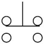
Break-make pushbutton switch:
- Break-before-make pushbutton is a switch whose top level section contacts are Normally Closed (NC) and bottom level section contacts are Normally Open (NO).
- The top level contacts will be opened before the bottom level contacts get closed when the pushbutton is pressed.
- An electrical symbol used to represent break-make pushbutton switch is given below.
Given:
The conventional hardwired relay circuit should perform the following circuit functions when two break-make pushbuttons are used.
- The light L1 must turn ON when pushbutton PB1 is pressed.
- The light L2 must turn ON when pushbutton PB2 is pressed.
- The pushbuttons must be interlocked electrically, such that L1 and L2 cannot be turned ON simultaneously.
Expert Solution & Answer
Want to see the full answer?
Check out a sample textbook solution
Students have asked these similar questions
Given the following Combinational circuit, Use Verilog HDL on Quartus tool to1. Write a Verilog HDL code to describe the module DCDR2×4 // this module name must be your last name ( younis2. Write a Verilog HDL code to describe the whole system structurally from its subsystems// this module name must be your university number ( 1181230)
Using the sim8085 write the following code:
In a sensor network, three pressure sensors are connected which gives the reading of 4 psi, 8 psi and 10 psi. All the sensor readings are to be summed up and store as a single reading
Computer Science
Show the code required to configure the high part of port B (From the Atmega 328P) as inputs and the low part as outputs, and enable the pull-up resistors of the 2 most significant inputs.
Show the code sequence that configures port D as input and port B as output, and then transfers the port information to port B.
Chapter 6 Solutions
PROGRAMMABLE LOGIC CONTROLLERS (LL)
Ch. 6 - Prob. 1RQCh. 6 - Prob. 2RQCh. 6 - Prob. 3RQCh. 6 - Prob. 4RQCh. 6 - Prob. 5RQCh. 6 - Prob. 6RQCh. 6 - Prob. 7RQCh. 6 - Prob. 8RQCh. 6 - What do the abbreviations NO and NC represent when...Ch. 6 - Prob. 10RQ
Ch. 6 - Prob. 11RQCh. 6 - Prob. 12RQCh. 6 - Compare the operation of a photovoltaic solar cell...Ch. 6 - What are the two basic components of a...Ch. 6 - Prob. 15RQCh. 6 - Give an explanation of how a scanner and a decoder...Ch. 6 - Prob. 17RQCh. 6 - Prob. 18RQCh. 6 - Prob. 19RQCh. 6 - Prob. 20RQCh. 6 - Prob. 21RQCh. 6 - Prob. 22RQCh. 6 - Prob. 23RQCh. 6 - Prob. 24RQCh. 6 - Prob. 25RQCh. 6 - Prob. 26RQCh. 6 - Prob. 27RQCh. 6 - Prob. 28RQCh. 6 - Prob. 29RQCh. 6 - Prob. 30RQCh. 6 - Prob. 31RQCh. 6 - Prob. 32RQCh. 6 - Prob. 33RQCh. 6 - Prob. 1PCh. 6 - Prob. 2PCh. 6 - Prob. 3PCh. 6 - Prob. 4PCh. 6 - Design a PLC program and prepare a typical I/O...Ch. 6 - Prob. 6PCh. 6 - Prob. 7PCh. 6 - Prob. 8P
Knowledge Booster

Similar questions
- 1. Design and implement a circuit using positive edge triggered DFFs that generates a pulse (p = 1) on the 2nd, 3rd, 5th, and 7th clock cycles after initialization. The sequence should repeat every 8 clock pulses. Include an asynchronous reset signal. 1.1 Implement your design in Verilog (behavioral)arrow_forwardDesign an appropriate combinational circuit that implements a digital system with the following output functions an AC remote: ON, OFF, MODE, SHIFT, FAN, SMART, SWING, ECO using a decoder.arrow_forwardDiscuss the Interface LED using General Purpose Input Output (GPIO) port. Investigate in further detail the operation of the GPIO ports on the MSP430F5529 Use control logic to manipulate outputs.arrow_forward
- Design and implement a minimal 5 up counter. It counts from 0 to 4 and repeats. Design the circuit such that, if the counter enters into the unwanted states: 5,6 and 7, it should jump into state 0 on the next clock pulse.arrow_forwarda) Build your circuit Design and build a state machine that will control the transition between light settings of a traffic light unit as shown in Figure 1. The design should include 3 positive edge triggered D flip-flops. Use 1 flip-flop to control the on and off of a given light, and the state machine should switch from Red (100) -> Red and Amber (110) - > Green (001) -> Amber (010) and repeat the cycle again, with the transition table below.arrow_forwardWhat unit of measurement is used to quantify the amount of work that a surges suppressormay perform before the circuit is no longer protected from an electrical surge?arrow_forward
- onstruct the state diagram, primitive flow table and reduced flow table for a fundamental mode circuit whose behaviour is as follows: Initial condition: Both the inputs and outputs are zero For x1 = 1 and x2 = 0; output (z) = 1 x1 = 0 and x2 = 1; output (z) = 0 x1x2 = 00 and x1x2 = 11; z = previous outpuarrow_forwardDevelop individual circuits and assembly code for the following scenarios: (12 points) (1) Using an LDR, turn the night lights automatically turn ON. (2) Sense the temperature using a sensor and turn ON the buzzer when the value is above a certain limit.arrow_forwardDraw the circuit and obtain the truth table of the VHDL module below module SAM(a, b, c, M, S);input a,b,c;output M;output S;wire d,e,f;xor(S,a,b,c);and(d,~a,b);and(e,b,c);and(f,~a,c);or(M,d,e,f);endmodulearrow_forward
- Question 1A microcontroller is used to control three LEDs in series (Blue, Red and White). Assume thecurrent rating is 50mA.1. Design an interfacing circuit for this purpose?2. List the required components and illustrate their purpose?3. What is the type of this interfacing?arrow_forwardDesign the interface for a positive logic switch to TM4C123GXL Port A pin 7. Show formulas and calculations for each circuit element. Draw the circuit schematics with components labelled with their names and values. Write the C code as a function to initialize the port for interfacing the switch. Write a function to read the data value of Port A pin 7. Comment your code to explain each initialization step clearly.arrow_forwardFigure 1 shows the circuit for a single digit common-cathode seven segment LED counter, that continually counts from 0 – 9. NB: When it reaches 9, it resets to zero and continue counting. 1. Write an AVR assembly code that implements the counter. Use a delay of 200 ms between the displays of each digit. sorry the website won't allow me to upload the image but the image is just showing a AVR ATTiny 2313 connected to a single digit common-cathode seven segment LED counter please give me a code that runs on Atmel studio 7 succesful and not in partsarrow_forward
arrow_back_ios
SEE MORE QUESTIONS
arrow_forward_ios
Recommended textbooks for you
 Database System ConceptsComputer ScienceISBN:9780078022159Author:Abraham Silberschatz Professor, Henry F. Korth, S. SudarshanPublisher:McGraw-Hill Education
 Starting Out with Python (4th Edition)Computer ScienceISBN:9780134444321Author:Tony GaddisPublisher:PEARSON
 Digital Fundamentals (11th Edition)Computer ScienceISBN:9780132737968Author:Thomas L. FloydPublisher:PEARSON
 C How to Program (8th Edition)Computer ScienceISBN:9780133976892Author:Paul J. Deitel, Harvey DeitelPublisher:PEARSON
 Database Systems: Design, Implementation, & Manag...Computer ScienceISBN:9781337627900Author:Carlos Coronel, Steven MorrisPublisher:Cengage Learning
 Programmable Logic ControllersComputer ScienceISBN:9780073373843Author:Frank D. PetruzellaPublisher:McGraw-Hill Education
Database System Concepts
Computer Science
ISBN:9780078022159
Author:Abraham Silberschatz Professor, Henry F. Korth, S. Sudarshan
Publisher:McGraw-Hill Education
Starting Out with Python (4th Edition)
Computer Science
ISBN:9780134444321
Author:Tony Gaddis
Publisher:PEARSON
Digital Fundamentals (11th Edition)
Computer Science
ISBN:9780132737968
Author:Thomas L. Floyd
Publisher:PEARSON
C How to Program (8th Edition)
Computer Science
ISBN:9780133976892
Author:Paul J. Deitel, Harvey Deitel
Publisher:PEARSON
Database Systems: Design, Implementation, & Manag...
Computer Science
ISBN:9781337627900
Author:Carlos Coronel, Steven Morris
Publisher:Cengage Learning
Programmable Logic Controllers
Computer Science
ISBN:9780073373843
Author:Frank D. Petruzella
Publisher:McGraw-Hill Education