
Concept explainers
Videos
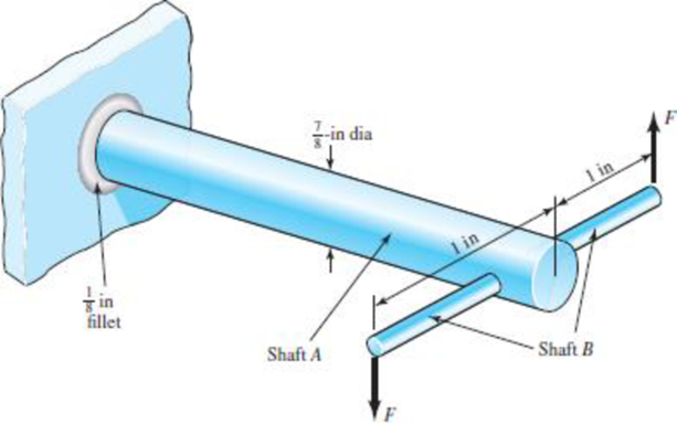
In the figure shown, shaft A, made of AISI 1020 hot-rolled steel, is welded to a fixed support and is subjected to loading by equal and opposite forces F via shaft B. A theoretical stress-concentration factor Kts of 1.6 is induced in the shaft by the
(a) For shaft A, find the factor of safety for infinite life using the modified Goodman fatigue failure criterion.
(b) Repeat part (a) using the Gerber fatigue failure criterion.
Problem 6–56

Trending nowThis is a popular solution!

Chapter 6 Solutions
MECH ENGINEERING DESIGN(LL)+ACCESS
Additional Engineering Textbook Solutions
Heat and Mass Transfer: Fundamentals and Applications
DESIGN OF MACHINERY
Degarmo's Materials And Processes In Manufacturing
Applied Statics and Strength of Materials (6th Edition)
HEAT+MASS TRANSFER:FUND.+APPL.
Statics and Mechanics of Materials


- 3. The hydraulic cylinder shown in the figure has a D = 6.7-cm bore and is to operateat a pressure of 11 MPa. With the clevis mount shown in figure for Q. No. 3, thepiston rod should be sized as a column with both ends rounded for any plane ofbuckling. The rod is to be made of forged AISI 1030 steel without further heattreatment.(a) Use a design factor nd = 2.5 and select a preferred size for the rod diameterif the column length is 2 m.(b) Repeat part (a) but for a column length of 51cm.(c) What factor of safety actually results for each of the cases above?arrow_forwardCalculate the maximum stress in the steel ring if a copper ring with a thread diameter of 2000 mm and a thickness of 20 mm and a steel ring with an inner diameter of 2000 mm and a thickness of 10 mm are interlocked and heated to 100°C. Scale= 100 GPa, Eçelik= 200 GPa, copper= 16.106/°C, steel= 12.10-6/°C a-) 20 MPa b-) 40 MPa c-) 50MPa d-) 60 MPa e-) 30 MPaarrow_forwardUsing the maximum-shear-stress (MSS) theory determine the factor of safety for a bar of AISI 1020 cold-drawn steel, see Table A-20) with the follwoing stresses: σx = 199 MPa, σy = 76 MPaarrow_forward
- In the figure shown, shaft A, made of steel (Sut = 469 MPa), is welded to a fixed support and is subjected to loading by equal and opposite forces F via shaft B. The length of shaft A from the fixed support to the connection at shaft B is 1 m. The load F cycles from -3.5 kN to 500 N. For shaft A, find the factor of safety for infinite life (using Case 3 safety factor calculation). Given: Corrected endurance limit Se = 235 MPa. Fatigue stress concentration factors in shear kfs = kfsm = 1.6.arrow_forwardA ho]]ow cinu]ar co]d-ro]]ed bronze ]Gi : 6,500 ksi] tube ( 1 ) with an outside diamctc'f of 1 .75 in. and an inside diam- eter of 1.25 in. is securely bonded to a solid 1.25-in.-diameter cold-rolled stainless steel IC! : 12,S00 ksil core (2) as shown in Figure . The allowable sham stress of tube ( 1 ) is 27 ksi. and the allowable shear stress of core (2) is 60 ksi. Determine (a) the allowable torque T that cm tv applied to the tube-and- corc assembly. (b) the corresponding torqucs produced in tube ( 1 ) and core (2). (c) the ' angle of twist produced in a IO-in. length of the aswmbly by the all(cable torque 71arrow_forwardFind factor of safety if the Ultimate Stress of a ductile material is 250.94 MPa. If the material is subjected to a loading condition that generates the working stress of 151.27 MPaarrow_forward
- In Figure 2 shown, shaft A, made of AISI 1010 hot-rolled steel, is welded to a fixed support and is subjected to loading by equal and opposite forces F via shaft B. A theoretical stress concentration Kt of 1.6 is induced by the 3-mm fillet. The length of shaft A from the fixed support to the connection at shaft B is 1 m. The load F cycles from 0.5 to 3. a) For shaft A, find the factor of safety for infinite life using the modified Goodman fatigue failure criterion. b) Repeat part (a) using the Gerber fatigue failure criterion.arrow_forwardA cylindrical steel pressure vessel has hemispherical emd caps. The inner radiuos of the vessel is 24 in anf the wall thickness is constant at o.25 in. When the vessel is presseured to 125 psi determine the following. A. The stresses of the cylinder r and hemispgerical caps. B. Based from the allowable working pressure of the blvessel solved in item a, if the pressure is increased to 250 psi what shall be the uniform thickness of the tankarrow_forwardThe figure gives the cross-section of a grade 25 cast-iron pressure vessel. A total of N bolts are to be used to resist a separating force of 150 kN. (a) Determine kb, km, and C. (b) Find the number of bolts required for a load factor of 2 where the bolts may be reused when the joint is taken apart. (c) With the number of bolts obtained in part (b), determine the realized load factor for overload, the yielding factor of safety, and the load factor for joint separation. Use (SI) units as it appliesarrow_forward
- Calculate the maximum working pressure (in MPa) of a fire tube boiler constructed using 8-mm thick steel plates with an ultimate tensile strength of 380 MPa. The boiler has a shape of a cylinder 2.85 m in dimeter with hemispherical ends. The longitudinal joints have an efficiency of 95%. A factor of safety equal to 5 was used in its design.arrow_forwardA rectangular steel plate is welded as a cantilever to a vertical column and supports a single concentrated load P. Determine the weld size if shear stress in the same is not to exceed 140 MPaarrow_forwardA solid 71-mm-diameter cold-rolled brass [G = 36.7 GPa] shaft that is 1.28 m long extends through and is completely bonded to a hollow aluminum [G = 25.9 GPa] tube. Aluminum tube (1) has an outside diameter of 95 mm, an inside diameter of 71 mm, and a length of 0.87 m. Both the brass shaft and the aluminum tube are securely attached to the wall support at A. Assume L1=L2 = 0.87 m, L3= 0.41 m, TB = 29 kN-m, and TC = 8 kN-m. When the two torques shown are applied to the composite shaft, determine:(a) the maximum shear stress magnitude T1 in aluminum tube(b) the maximum shear stress magnitude T2 and T3 in brass shaft segment(c) the rotation angle of joint B and joint Carrow_forward
 Mechanics of Materials (MindTap Course List)Mechanical EngineeringISBN:9781337093347Author:Barry J. Goodno, James M. GerePublisher:Cengage Learning