
MECH ENGINEERING DESIGN(LL)+ACCESS
10th Edition
ISBN: 9781260113952
Author: BUDYNAS
Publisher: MCG
expand_more
expand_more
format_list_bulleted
Concept explainers
Videos
Textbook Question
Chapter 6, Problem 17P
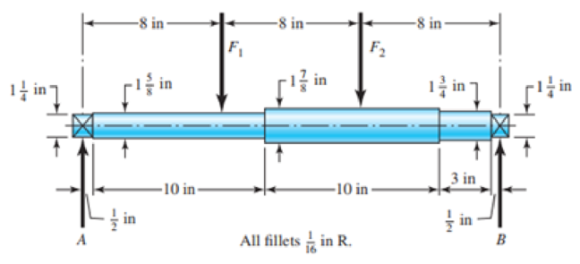
The shaft shown in the figure is machined from AISI 1010 CD steel. The shaft rotates at 1600 rpm and is supported in rolling bearings at A and B. The applied forces are F1 = 2500 Ibf and F2 = 1000 Ibf. Determine the minimum fatigue factor of safety based on achieving infinite life. If infinite life is not predicted, estimate the number of cycles to failure. Also check for yielding.
Problem 6-17
Expert Solution & Answer
Want to see the full answer?
Check out a sample textbook solution
Students have asked these similar questions
The figure shows a shaft mounted in bearings at A and D and having pulleys at B and C. The forces shown acting on the pulley surfaces represent the belt tensions. The shaft is to be made of AISI 1035 CD steel. The shaft is rotating at speed of 1000 rpm. Find the minimum factor of safety for fatigue based on infinite life. If the life is not infinite, estimate the number of cycles. Be sure to check for yielding. Take shaft diameter to be 1.5 inches.
The rotating shaft running at n = 900 rpm, shown in the figure below, is machined from AISI 1045 CD steel. It is subjected to a force of F = 10.1 kN. The shaft is experiencing an operating temperature of 35 oC. With the specified loading and for the reliability of 99.9 %,
Determine the minimum factor of safety for fatigue based on infinite life*.
Determine the maximum safe load (Fmax) that can be applied for a factor of safety of 1.5 and a design life of 5x10⁵ cycles, all other input values remaining the same.
Determine the factor of safety against yielding.
The solid steel rotating shaft in the figure is supported at B and C, and is driven by a gear, not seen, which is linked to spur gear D which has a pitch diameter of 150 mm. The drive gear force F acts at a pressure angle of 20 degrees. The shaft transmits a torque to point A of Ta-350 N.m. The properties of machined steel shaft are Sy-420 MPa and Sut-560MPa. Use a safety factor of 2.5 and determine the minimum allowable diameter in section B and C. Assume sharp felt radii at the bearing shoulders to estimate the stress concentration factors.Explain.
Chapter 6 Solutions
MECH ENGINEERING DESIGN(LL)+ACCESS
Ch. 6 - A 10-mm steel drill rod was heat-treated and...Ch. 6 - Prob. 2PCh. 6 - A steel rotating-beam test specimen has an...Ch. 6 - A steel rotating-beam test specimen has an...Ch. 6 - A steel rotating-beam test specimen has an...Ch. 6 - Repeat Prob. 6-5 with the specimen having an...Ch. 6 - A steel rotating-beam test specimen has an...Ch. 6 - Derive Eq. (6-17). Rearrange the equation to solve...Ch. 6 - For the interval 103 N 106 cycles, develop an...Ch. 6 - Estimate the endurance strength of a...
Ch. 6 - Two steels are being considered for manufacture of...Ch. 6 - A 1-in-diamctcr solid round bar has a groove...Ch. 6 - A solid square rod is cantilevered at one end. The...Ch. 6 - A rectangular bar is cut from an AISI 1020...Ch. 6 - A solid round bar with diameter of 2 in has a...Ch. 6 - The rotating shaft shown in the figure is machined...Ch. 6 - The shaft shown in the figure is machined from...Ch. 6 - Solve Prob. 6-17 except with forces F1 = 1200 lbf...Ch. 6 - Bearing reactions R1 and R2 are exerted on the...Ch. 6 - A bar of steel has the minimum properties Se = 40...Ch. 6 - Repeat Prob. 6-20 but with a steady torsional...Ch. 6 - Repeat Prob. 6-20 but with a steady torsional...Ch. 6 - Repeat Prob. 6-20 but with an alternating...Ch. 6 - A bar of steel has the minimum properties Se = 40...Ch. 6 - The cold-drawn AISI KUO steel bar shown in the...Ch. 6 - Repeat Prob. 6-25 for a load that fluctuates from...Ch. 6 - An M14 2 hex-head bolt with a nut is used to...Ch. 6 - The figure shows a formed round-wire cantilever...Ch. 6 - The figure is a drawing of a 4- by 20-mm latching...Ch. 6 - The figure shows the free-body diagram of a...Ch. 6 - Solve Prob. 6-30 except let w1 = 2.5 in. w2 = l.5...Ch. 6 - For the part in Prob. 630, recommend a fillet...Ch. 6 - Prob. 33PCh. 6 - Prob. 34PCh. 6 - A part is loaded with a combination of bending,...Ch. 6 - Repeat the requirements of Prob. 6-35 with the...Ch. 6 - 6-37 to 6-46For the problem specified in the build...Ch. 6 - 6-37 to 6-46For the problem specified in the build...Ch. 6 - 637 to 646 For the problem specified in the table,...Ch. 6 - For the problem specified in the table, build upon...Ch. 6 - 6-37 to 6-46 For the problem specified in the...Ch. 6 - 6-37 to 6-46 For the problem specified in the...Ch. 6 - 6-37 to 6-46 For the problem specified in the...Ch. 6 - Problem Number Original Problem, Page Number 637...Ch. 6 - 6-37 to 6-46 For the problem specified in the...Ch. 6 - 6-37 to 6-46 For the problem specified in the...Ch. 6 - 6-47 to 6-50 For the problem specified in the...Ch. 6 - 6-47 to 6-50 For the problem specified in the...Ch. 6 - Prob. 49PCh. 6 - Prob. 50PCh. 6 - 6-51 to 6-53 For the problem specified in the...Ch. 6 - 6-51 to 6-53 For the problem specified in the...Ch. 6 - 6-51 to 6-53 For the problem specified in the...Ch. 6 - Solve Prob. 6-17 except include a steady torque of...Ch. 6 - Solve Prob. 618 except include a steady torque of...Ch. 6 - In the figure shown, shaft A, made of AISI 1020...Ch. 6 - A schematic of a clutch-testing machine is shown....Ch. 6 - For the clutch of Prob. 657, the external load P...Ch. 6 - A flat leaf spring has fluctuating stress of max =...Ch. 6 - A rotating-beam specimen with an endurance limit...Ch. 6 - A machine part will be cycled at 350 MPa for 5...Ch. 6 - The material properties of a machine part are Sut...Ch. 6 - Repeat Prob. 662 using the Goodman criterion....
Knowledge Booster


Learn more about
Need a deep-dive on the concept behind this application? Look no further. Learn more about this topic, mechanical-engineering and related others by exploring similar questions and additional content below.Similar questions
- The shaft shown in the figure is machined from AISI 1040 CD steel. The shaft rotates at 1600 rpm and is supported in rolling bearings at A and B. The applied forces are F1 = 1600 lbf and F2 = 640 lbf. A steady torque of 1600 lbf·in is being transmitted through the shaft between the points of application of the forces. ——————————————- Determine the endurance limit for this material as well as the value after correction for surface finish, sizing, and loading. (You must provide an answer before moving to the next part.) The endurance limit for this material is kpsi. The value after correction for surface finish, sizing, and loading is kpsi.arrow_forwardIn the figure, a steel shaft with ball bearings at points A and D, with cross-section narrowing at points C and D, a single load of 2 kN from B point not to rotate with the shaft, 0.1 kN/mm between points D and E so that it does not rotate together with the shaft. A distributed load of ' is applied. The shaft surface is ground and the shaft operates at room temperature with 50% reliability. Calculate the fatigue life of the shaft, taking into account the cross section narrowing point where the maximum moment occurs. All radii on the shaft are R2 mm.(Sut=690 MPa,f=0.9)arrow_forwardThe figure shows a shaft mounted in bearings at A and D and having pulleys at B and C. The forces shown acting on the pulley surfaces represent the belt tensions. The shaft is to be made of AISI 1035 CD steel. Using distortion-energy theory with a design factor of 2, determine the minimum shaft diameter to avoid yielding.arrow_forward
- A rotating shaft of 40×4 mm AISI 1018 cold-drawn steel tubing has a 6 mm diameter hole drilled transversely through it. Estimate the factor of safety guarding against fatigue and static failures using the Gerber and Langer failure criteria for the following loading conditions: a. The shaft is subjected to a completely reversed torque of 120 N.m in phase with a completely reversed bending moment of 150 N.m. b. The shaft is subjected to a pulsating torque fluctuating from 20 to 160 N.m and as steady bending moment of 150 N.m.arrow_forwardThe shaft shown in the figure is machined from AISI 1040 CD steel. The shaft rotates at 1600 rpm and is supported in rolling bearings at A and B. The applied forces are F1 = 1600 lbf and F2 = 640 lbf. A steady torque of 1600 lbf·in is being transmitted through the shaft between the points of application of the forces.arrow_forwardAn input shaft of a gearbox with motor power P = 7 kW and rotation number n = 1300 rpm. The diameter of an input shaft is d = 20 mm and its material is 16MnCr5. A force of F = 2800 N forces the shaft due to the operation of a gear wheel connected with a wedge on the input shaft. The distances of the gear from the bearings are given as L₁ = 40 mm and L2 = 60 mm. In the most dangerous section, you are required to check the strength according to the S = 3 safety factor. If the section is unsafe in terms of strength, what changes would you make in the design to make it safe? (The surface of the spindle is machined as fine chips, reliability poor Kg = 1.).arrow_forward
- The shaft in the figure is mounted with a gear wheel key. Shaft material 42CrMo4 The weight of the gear on the shaft is 0.9 kg, dimension, surface and notch factors KbK / Kç = 0.83, shaft speed n = 1120 rpm, shaft transmitted power 7.5 kW, force on shaft Fn = F = 2680 N Since the desired safety coefficient is Ssafe = 2; Check the safety of the shaftarrow_forwardA Steel shaft is subjected to an end thrust producing a stress of 90 MPa and the minimum shearing stress on the surface arising from torsion is 60 MPa .The yield point stress of the material in simple tension was found to be 300 MPa. calculate the factor of safety of the shaft according to the following theory 1)maximum shear stress theoryarrow_forwardA screw clamp shown in the figure has a handle with diameter 5 mm made of cold-drawn AISI 1006 steel (table E18 - page 1195). The overall length of the hand is 75 mm. The screw is M 12 coarse (table 8-1) and is 145 mm long, overall. Distance A is 50 mm. The clamp will accommodate parts up to 105 mm high.a) What is the value of screw torque that causes the handle to bend permanently?b) If the collar friction is neglected and if the thread friction is 0.075, what is the screw force value that causes the handle to bend permanently?c) What is the value of clamping force, which will cause the screw to buckle?d) Are there any other stresses or possible failures to be checked?e) If yes, calculate them.arrow_forward
- A rotating shaft of 25-mm diameter is simply supported by bearing reaction forces R1 and R2. The shaft is loaded with a transverse load of 13 kN as shown in the figure. The shaft is made from AISI 1045 hot-rolled steel. The surface has been machined. Determine a) The minimum static factor of safety based on yielding b) the endurance limit adjusted as necessary with Marin factors c) the minimum fatigue factor of safety based on achieving infinite life d) if the fatigue factor of safety is less than 1, then estimate the life of the part in number of rotationsarrow_forwardCalculate the maximum tensile stress developed in a 1/4-20 bolt (Major dia = 0.2500" and Root dia = 0.1959"), 3" long, and a head height of 0.1875", if it is subjected to a load of 426 lbs.arrow_forwardA motor is to transmit 150 kW to a piece of mechanical equipment. The power is transmitted through a solid structural steel shaft. Failure is by yielding, and the factor of safety is 1.25. The designer has the freedom to operate the motor at 60 rpm or 6000 rpm. For each case, determine the minimum shaft diameter. Shafts are available with diameters in increments of 5 mm. If weight is important, which speed would be used?arrow_forward
arrow_back_ios
SEE MORE QUESTIONS
arrow_forward_ios
Recommended textbooks for you
 Mechanics of Materials (MindTap Course List)Mechanical EngineeringISBN:9781337093347Author:Barry J. Goodno, James M. GerePublisher:Cengage Learning
Mechanics of Materials (MindTap Course List)
Mechanical Engineering
ISBN:9781337093347
Author:Barry J. Goodno, James M. Gere
Publisher:Cengage Learning
Everything About COMBINED LOADING in 10 Minutes! Mechanics of Materials; Author: Less Boring Lectures;https://www.youtube.com/watch?v=N-PlI900hSg;License: Standard youtube license