Concept explainers
Videos
The expression for extrusion pressure.
Explanation of Solution
The figure (1) demonstrate the forces on the specimen in a wire drawing process.
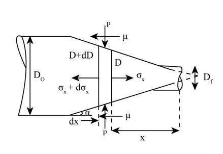
Figure (1)
The expression for the equilibrium in x direction can be given as,
Here, pressure along the die contact is
After expanding the above equation,
Further solving the above equation,
Expression for pressure
Substituting the value of
Integration of equation (2) for boundary condition
Simplifying the above equation,
The expression for the ratio of area,
Substituting the above value in the equation (3),
For,
Conclusion:
Therefore, the equation is
Want to see more full solutions like this?
Chapter 6 Solutions
Pearson eText for Manufacturing Processes for Engineering Materials -- Instant Access (Pearson+)


- ELECTRICAL ENGINNERING THANK YOU SO MUCHarrow_forwardIn a wire drawing process, the length of the wire at any instant is given by L(t) = L,(1+) where t is the time in minutes and L, is the initial length. The true strain rate at the end of 0.5 min (in min-!) isarrow_forward2. A metal alloy has been tested in a tensile test with the following results for the flow curve parameters: strength coefficient = 620.5 MPa and strain-hardening exponent 0.26. The same metal is now tested in a compression test in which the starting height of the specimen = 62.5 mm and its diameter = 25 mm. Assuming that the cross section increases uniformly, determine the load required to compress the specimen to a height of (a) 50 mm and (b) 37.5 mm. 3. The starting length of a shaft is 25.00 mm. This shaft is to be inserted into a hole in an expansion fit assembly operation. To be readily inserted, the shaft must be reduced in length by cooling. Determine the temperature to which the shaft must be reduced from room temperature (20° C) in order to reduce its length to 24.98 mm. Refer to the Table below. Volumetric properties in U.S. customary units for selected engineering materials. Coefficient of Thermal Expansion, a Density, p Ib/in Melting Point, T Material g/cm C'x 10 F'x 10 6…arrow_forward
- 2. A metal alloy has been tested in a tensile test with the following results for the flow curve parameters: strength coefficient = 620.5 MPa and strain-hardening exponent = 0.26. The same metal is now tested in a compression test in which the starting height of the specimen = 62.5 mm and its diameter 25 mm. Assuming that the cross section increases uniformly, determine the load required to compress the specimen to a height of (a) 50 mm and (b) 37.5 mm.arrow_forwardMetal Forming Processesarrow_forward1 %AV l. 1:Y0 A docs.google.com/forms/d/e مختبر ميكانيك المواد Why used two equipment in shear force and bending moment experiment (one for ?S.F and the other to B.M) إجابتك What is the relationship between the ?distance from neutral axis and stress إجابتك Explain in steps with detail, how can find the ?Young's modulus for any unknown beam إجابتك What is the meaning of + S.F, -S.F, +B.M and ?- B.M إجابتك صفحة 4 من 5 IIarrow_forward
- No wrong answer please , i could downvote The piece of suture is tested for its stress relaxation properties after cutting 3 cm long sample with a diameter of 1mm. The initial force recorded after stretching 0.1 cm between grips was 5 Newtons. Assume the suture material behave as if it has one relaxation time. The gage length was 1 cm. a. Calculate the initial stress. b. Calculate the initial strain. c. Calculate the modulus of elasticity of the suture if the initial stretching can be considered as linear and elastic. d. Calculate the relaxation time if the force recorded after 10 hours is 4 Newtons.arrow_forwardEquation 6.16: εT = ln(li / l0)arrow_forwardMath Inking Pens Convert Close 6 5.. 4 3... 2. . 1.. 5y,200 IN %3D 1 m? 10 mm = 6.6 x 10 N/m2 = 660 MPa (95,700 psi) A (89.9 mm?)(- Eхample A 13 mm-diameter tensile specimen has a 50 mm gage length. The load corresponding to the 0.2 percent offset is 6800 kg and the maximum load is 1800 kg. Fracture occurs at 7300 kg. The diameter after fracture is 8 mm and the gage length at fracture is 65 mm. calculate the standard properties of the material from the tension test. BY: Ali Abdulsalamarrow_forward
- The relationship between true strain (ɛ-) and engineering strain (ɛ) in a uniaxial tension test is given as (a) & = In (1 + &7) (c) &7= In (1+ E) (b) ɛg = In (1- E) (d)= in (1- E) %3D %3Darrow_forwardAnswer both partsarrow_forwardTensile test is a method to investigate the elasticity of a material. A test specimen is placed between two clamps and these clamps will move in opposite directions, hence straining the test specimen. This experiment will yield a stress-strain curve that shows each of the stages of the specimen for every load is applied. With an aid of sketching diagrams, describe the stages that the specimen experiences before it breaks, and relate it with the stress-strain curve. It is expected that each stage comes with a sketching of the specimen and explanation of the current stage.arrow_forward
 Elements Of ElectromagneticsMechanical EngineeringISBN:9780190698614Author:Sadiku, Matthew N. O.Publisher:Oxford University Press
 Mechanics of Materials (10th Edition)Mechanical EngineeringISBN:9780134319650Author:Russell C. HibbelerPublisher:PEARSON
 Thermodynamics: An Engineering ApproachMechanical EngineeringISBN:9781259822674Author:Yunus A. Cengel Dr., Michael A. BolesPublisher:McGraw-Hill Education
 Control Systems EngineeringMechanical EngineeringISBN:9781118170519Author:Norman S. NisePublisher:WILEY
 Mechanics of Materials (MindTap Course List)Mechanical EngineeringISBN:9781337093347Author:Barry J. Goodno, James M. GerePublisher:Cengage Learning
 Engineering Mechanics: StaticsMechanical EngineeringISBN:9781118807330Author:James L. Meriam, L. G. Kraige, J. N. BoltonPublisher:WILEY