
Concept explainers
Videos
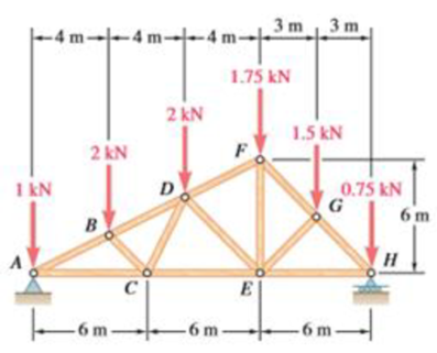
Using the method of joints, determine the force in each member of the double-pitch roof truss shown. State whether each member is in tension or compression.
The force in each of the member of the double-pitch roof truss using method of joints and whether each member is in tension or compression.
Answer to Problem 6.165RP
The force in member
Explanation of Solution
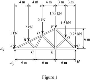
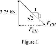
The free-body diagram of the truss is shown in figure 1.
The sum of the moments about the point
Here,
Write the equation for
Here,
Put the above equation in equation (I).
The
Here,
Write the expression for
Here,
Put the above equation in equation (II).
The
Here,
Write the expression for
Put the above equation in equation (III).
Here,
Substitute
The free-body diagram of joint A is shown in figure 2.
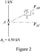
The joint A is subject to the forces exerted by
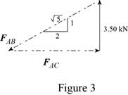
Obtain the magnitudes of the two forces from proportion.
Here,
The free-body diagram of the joint B is shown in figure 4.
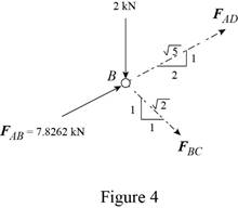
Write the equilibrium equations.
Here,
Write the expression for
Here,
Put the above equation in equation (IV).
The
Here,
Write the expression for
Put the above equation in equation (VI).
Multiply equation (V) by
Subtract equation (VII) from (V).
The free-body diagram of the joint C is shown in figure 5.
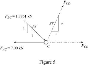
Write the expression for
Here,
Put the above equation in equation (VI).
Write the expression for
Here,
Put the above equation in equation (IV).
The free-body diagram of the joint D is shown in figure 6.
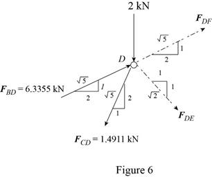
Write the expression for
Here,
Put the above equation in equation (IV).
Write the expression for
Put the above equation in equation (VI).
Add equations (VIII) and (IX).
Subtract equation (IX) from equation (VIII).
Consider the joint F. The free-body diagram of the joint F is shown in figure 7.
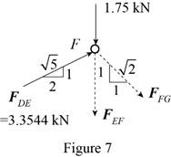
Write the expression for
Here,
Put the above equation in equation (IV).
Write the expression for
Here,
Put the above equation in equation (VI).
Consider the joint G. The free-body diagram of the joint G is shown in figure 8.
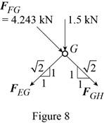
Write the expression for
Here,
Put the above equation in equation (IV).
Write the expression for
Put the above equation in equation (VI).
Add equations (X) and (XI).
Subtract equation (X) from equation (XI).
Consider the joint H. The free-body diagram of the joint H is shown in figure 9.
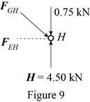
The joint H is subject to the forces exerted by
Obtain the magnitudes of the force from proportion.
Conclusion:
Thus, the force in member
Want to see more full solutions like this?
Chapter 6 Solutions
Vector Mechanics for Engineers: Statics


 Elements Of ElectromagneticsMechanical EngineeringISBN:9780190698614Author:Sadiku, Matthew N. O.Publisher:Oxford University Press
 Mechanics of Materials (10th Edition)Mechanical EngineeringISBN:9780134319650Author:Russell C. HibbelerPublisher:PEARSON
 Thermodynamics: An Engineering ApproachMechanical EngineeringISBN:9781259822674Author:Yunus A. Cengel Dr., Michael A. BolesPublisher:McGraw-Hill Education
 Control Systems EngineeringMechanical EngineeringISBN:9781118170519Author:Norman S. NisePublisher:WILEY
 Mechanics of Materials (MindTap Course List)Mechanical EngineeringISBN:9781337093347Author:Barry J. Goodno, James M. GerePublisher:Cengage Learning
 Engineering Mechanics: StaticsMechanical EngineeringISBN:9781118807330Author:James L. Meriam, L. G. Kraige, J. N. BoltonPublisher:WILEY