
Concept explainers
Videos
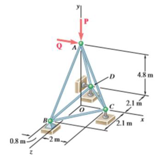
The truss shown consists of six members and is supported by a ball and socket at B, a short link at C, and two short links at D. Determine the force in each of the members for P= (−2184 N)j and Q = 0.
The force in each of the members of the truss for
Answer to Problem 6.36P
The force in member AC is
Explanation of Solution
The free-body diagram of the entire truss is shown in figure 1.
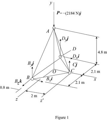
Refer to figure 1 and use symmetry.
Here,
The
Here,
Write the expression for
Put the above equation in equation (II).
Put equation (I) in the above equation.
The
Here,
Write the expression for
Here,
Put the above equation in equation (III).
Write the equilibrium equations taking the moments about the point C in the
Here,
Write the equation for
Put the above equation in equation (IV).
Write the expression for the reaction at the point B.
Here
Substitute
Consider the free-body joint A. The free-body diagram of joint A is shown in figure 2.
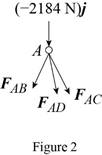
Refer to figure (2) and write the expression for the forces.
Here,
Write the expression for
Find the magnitude of
Substitute
Write the expression for
Here,
Substitute
Write the expression for
Here,
Substitute
The net force must be equal to zero.
Here,
Write the expression for
Put the above equation in equation (IX).
Put equations (VI), (VII) and (VIII) in the above equation.
Equate the coefficient of
Equate the coefficient of
Equate the coefficient of
Multiply equation (XI) by
Put equation (XIII) in equation (XI).
Substitute
Put the above equation in equation (XIII).
Consider the free-body joint B. The free-body diagram of joint B is shown in figure 3.
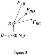
Refer to figure (3) and write the expression for the forces.
Substitute
Write the expression for
Here,
Substitute
Write the expression for
Here,
Write the expression for
Put the above equation in equation (IX).
Put equations (XIV), (XV) and (XVI) in the above equation.
Substitute
Equate the coefficient of
Equate the coefficient of
Substitute
From symmetry,
Here,
Substitute
Conclusion:
Thus, the force in member AC is
Want to see more full solutions like this?
Chapter 6 Solutions
Vector Mechanics for Engineers: Statics


- Determine the force in each member of the truss, and indicate whether the members are in tension or compression.arrow_forwardDetermine the force in each member of the truss and state if the members are in tension or compression.Set P1=9kN , P2=15kN.Using the principle of static equilibrium of moments.arrow_forwardDetermine the force in members FG, FH, and HG of the truss which serves to support the deck of a bridge if P1 = 50kN, P2 = 20kN and P3 = 10kN. State if these members are in tension or compression.arrow_forward
- Determine the force in the members' AB, AE, AF, BC, BE, CD, CE, DE, EF, and state if each member is in tension or compression. P1=9kN and P2=14kNarrow_forwardDetermine the force in each member of the truss and state if the members are in tension or compression. Set P1 = 9 kN, P2 = 15 kN. using the principle of static equilibrium of momentsarrow_forwardDetermine the force in each member . Indicate whether each member is in tension ( T ) or compressive ( C ).arrow_forward
- Classify each of the structures shown as completely, partially, or improperly constrained; if completely constrained, further classify as determinate or indeterminate. (All members can act both in tension and in compression.)arrow_forwardUsing the method of joints, determine the force in each member of the truss.arrow_forwardDetermine the forces in each member of the right half of the truss using the method of joints. Given: F1=5 kN F2=12 kN F3=4 kN F4= 11 kN L=8 marrow_forward
- Q1:a- Identify the zero-force members in the truss. b- Determine the force in each member of the truss using Method of Joints. State if the members are in tension or compression. F = 7 kNarrow_forwardThe jib crane is pin connected at A and supported by a pin connected collar on smooth rod at B. If x = 6.0 ft , determine the reactions on the jib crane at the pin A and smooth collar B. The load has a weight of 5500 lb Determine the reactions on the jib crane at the pin A Determine the reaction at Barrow_forwardThe figure below shows a truss (a = 1 m), which is loaded by a force F = 2 kN. a) Determine the forces in the members S1, S4, S5, S6, S9 and S10.arrow_forward
 Elements Of ElectromagneticsMechanical EngineeringISBN:9780190698614Author:Sadiku, Matthew N. O.Publisher:Oxford University Press
 Mechanics of Materials (10th Edition)Mechanical EngineeringISBN:9780134319650Author:Russell C. HibbelerPublisher:PEARSON
 Thermodynamics: An Engineering ApproachMechanical EngineeringISBN:9781259822674Author:Yunus A. Cengel Dr., Michael A. BolesPublisher:McGraw-Hill Education
 Control Systems EngineeringMechanical EngineeringISBN:9781118170519Author:Norman S. NisePublisher:WILEY
 Mechanics of Materials (MindTap Course List)Mechanical EngineeringISBN:9781337093347Author:Barry J. Goodno, James M. GerePublisher:Cengage Learning
 Engineering Mechanics: StaticsMechanical EngineeringISBN:9781118807330Author:James L. Meriam, L. G. Kraige, J. N. BoltonPublisher:WILEY