
Concept explainers
Videos
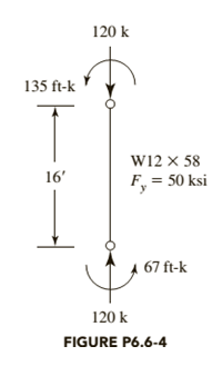
The member shown in Figure P6.6-4 is part of a braced frame. The load and moments are computed from service loads, and bending is about the
a. Use LRFD.
b. Use ASD.

Trending nowThis is a popular solution!

Chapter 6 Solutions
Steel Design (Activate Learning with these NEW titles from Engineering!)


- Determine the displacement and the rotational at point D, considering that the moment of inertia I=300 in4, the elastic modulus is the same for the section of the beam with a value of E=29000 Ksi. Use Castigliano's method for beams. Point D is half the distance from segment AB. The following figure shows the applied loads, distances, and conditions at the beam supports.arrow_forwardAnswer is -66.35. No other answer thanks. A roof truss is shown in the figure and loaded as such. If force P = 93.84 kN, find the force in member BC (in kN). Neglect H1, H2, and H3. Use a = 4 m., and b = 6 m.arrow_forwardGiven the problem: 1.) In the frame, shown, members 'ACE' and 'BCD' are connected by a pin at 'C' and by the link 'DE'. For the loading shown, determine this: d.) Vertical component at ‘C’ on member ‘BCD’ in N.e.) Total force exerted at ‘C’ on member ‘BCD’ in N. *Round off final answer in 4 decimal places. Thank you.arrow_forward
- Determine the internal forces and a couple moments at point B of the beam shown in the figure. Show your FBD clearly.arrow_forwardThe rigid bar BDE is supported by two links AB and CD. Link AB is made of aluminum (E = 70 GPa) and has a cross-sectional area of 512 mm2; link CE is made of steel (E = 200 GPa) and has a cross-sectional area of 643 mm2. For the 32 kN force shown, determine the deflection of D (mm) *Note: Negative if compression and positive if tension. Also, the final answer should have two decimal places.arrow_forwardA beam is subjected to equal bending moments of Mz = 55kipft The cross-sectional dimensions are b1= 6.3 in.. d1 = 1.5in b2 = 0.6in d2 = 6.2in b3 = 2.8in and d3= 2.2in Determine: (a) the centroid location (measured with respect to the bottom of the cross-section), the moment of inertia about the z axis, and the controlling section modulus about the z axis. (b) the bending stress at point H. Tensile stress is positive, while compressive stress is negative. (c) the bending stress at point K. Tensile stress is positive, while compressive stress is negative. (d) the maximum bending stress produced in the cross section. Tensile stress is positive. while compressive stress is negative.arrow_forward
- Solve the shear moment diagram of the beams using Method of Section ONLY. Show your step by step solution. P= 85 lb ; B= 50 lb ; M= 140 ft-lbDistance between B to M is 5ftarrow_forwardThe frame has loads P₁ = 8.2 kN, P₂ = 8.7 kN, and P3 = 6.1 kN. Assume Joint B is rigid-connected and Joint C is pin- connected. Both Supports A and D are hinges. Determine the magnitude of the shear force at right of Beam BC (at Joint C). Please provide your answer in kN and to two decimal points. Answer:arrow_forwarda. For the frame shown above, with the loading as shown, the vertical reaction at J is equal to 36 kN pointing vertically downwards. Use the method of joints to calculate the force in member FJ in kN. b. Use the method of sections to calculate the force in member CB in kN.arrow_forward
- Analyze the beam by stiffness as shown in figure 5 and draw SFD and BMD. Take point load P =36arrow_forwardFor the truss shown in the figure, determine the force acting in the member BC. Use P = 437 kN. Indicate if the member is under compression (-) or tension (+).arrow_forwardFOR FIG REFER ATTACHED FILEThe shaft is massless. A thin attached triangular mass ‘m’ is mounted on the shaft. Rotational speed of the shaft is ω. Neglect weight effect of attached mass. Bearings are at A and B.Take Z- axis along the shaft axis. X- axis is vertically downward. Y – axis is horizontal. Take origin at mid-point on the shaft (As shown in fig). QUESTIONS: Rotate the shaft by 90 degrees and using the moment equation about ‘A’ and force equation to obtain the bearing reactions at‘A’ and ‘B’.arrow_forward

 Structural Analysis (10th Edition)Civil EngineeringISBN:9780134610672Author:Russell C. HibbelerPublisher:PEARSON
 Principles of Foundation Engineering (MindTap Cou...Civil EngineeringISBN:9781337705028Author:Braja M. Das, Nagaratnam SivakuganPublisher:Cengage Learning
 Fundamentals of Structural AnalysisCivil EngineeringISBN:9780073398006Author:Kenneth M. Leet Emeritus, Chia-Ming Uang, Joel LanningPublisher:McGraw-Hill Education
 Traffic and Highway EngineeringCivil EngineeringISBN:9781305156241Author:Garber, Nicholas J.Publisher:Cengage Learning