
Videos
(a)
The force vs. reduction in height curve in open die forging of cylinder.
(a)
Explanation of Solution
Given:
The initial thickness of the specimen is
The initial diameter of the specimen is
The friction coefficient is
Formula used:
The expression for the flow stress is given as,
Here,
The expression for the true strain is given as,
Here,
The expression for the final radius by equating the volume is given as,
The expression for the forging force is given as,
Here,
The expression for final height for
The expression for final height for
The expression for final height for
The expression for final height for
The expression for final height for
The expression for final height for
The expression for final height for
Calculation:
Refer to table 2.2 “Typical values of strength coefficient
The flow stress can be calculated as,
The true strain can be calculated as,
Obtain the expression by substituting equation 2 in 1,
The final radius can be calculated as,
The average pressure can be calculated as,
The forging force can be calculated as,
For
The final height for
The final radius can be calculated by substituting the values in equation 4,
The forging force can be calculated at
For
The final height for
The final radius can be calculated by substituting the values in equation 4,
The forging force can be calculated at
For
The final height for
The final radius can be calculated by substituting the values in equation 4,
The forging force can be calculated at
For
The final height for
The final radius can be calculated by substituting the values in equation 4,
The forging force can be calculated at
For
The final height for
The final radius can be calculated by substituting the values in equation 4,
The forging force can be calculated at
For
The final height for
The final radius can be calculated by substituting the values in equation 4,
The forging force can be calculated at
For
The final height for
The final radius can be calculated by substituting the values in equation 4,
The forging force can be calculated at
The plot between forging force and reduction in height is shown in figure (1) below,
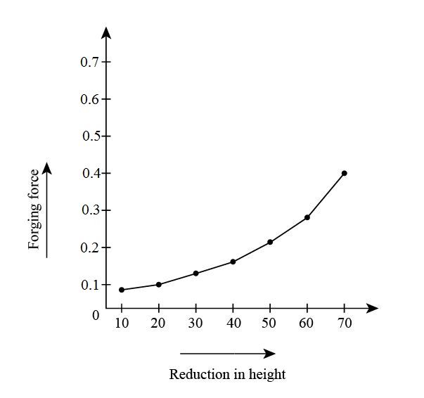
Figure (1)
The force vs. reduction in height curve in open die forging of cylinder.
Answer to Problem 6.74P
The force vs. reduction in height curve in open die forging of cylinder.
Explanation of Solution
Calculation:
Refer to table 2.2 “Typical values of strength coefficient
The flow stress can be calculated as,
The true strain can be calculated as,
Obtain the expression by substituting equation 2 in 1,
The final radius can be calculated as,
The average pressure can be calculated as,
The forging force can be calculated as,
For
The final height for
The final radius can be calculated by substituting the values in equation 4,
The forging force can be calculated at
For
The final height for
The final radius can be calculated by substituting the values in equation 4,
The forging force can be calculated at
For
The final height for
The final radius can be calculated by substituting the values in equation 4,
The forging force can be calculated at
For
The final height for
The final radius can be calculated by substituting the values in equation 4,
The forging force can be calculated at
For
The final height for
The final radius can be calculated by substituting the values in equation 4,
The forging force can be calculated at
For
The final height for
The final radius can be calculated by substituting the values in equation 4,
The forging force can be calculated at
For
The final height for
The final radius can be calculated by substituting the values in equation 4,
The forging force can be calculated at
The plot between forging force and reduction in height is shown in figure (2) below,
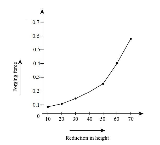
Figure (2)
The force vs. reduction in height curve in open die forging of cylinder.
Explanation of Solution
Calculation:
Refer to table 2.2 “Typical values of strength coefficient
The flow stress can be calculated as,
The true strain can be calculated as,
Obtain the expression by substituting equation 2 in 1,
The final radius can be calculated as,
The average pressure can be calculated as,
The forging force can be calculated as,
For
The final height for
The final radius can be calculated by substituting the values in equation 4,
The forging force can be calculated at
For
The final height for
The final radius can be calculated by substituting the values in equation 4,
The forging force can be calculated at
For
The final height for
The final radius can be calculated by substituting the values in equation 4,
The forging force can be calculated at
For
The final height for
The final radius can be calculated by substituting the values in equation 4,
The forging force can be calculated at
For
The final height for
The final radius can be calculated by substituting the values in equation 4,
The forging force can be calculated at
For
The final height for
The final radius can be calculated by substituting the values in equation 4,
The forging force can be calculated at
For
The final height for
The final radius can be calculated by substituting the values in equation 4,
The forging force can be calculated at
The plot between forging force and reduction in height is shown in figure (3) below,
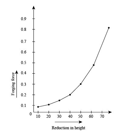
Figure (3)
Want to see more full solutions like this?
Chapter 6 Solutions
EBK MANUFACTURING PROCESSES FOR ENGINEE


- What is K constant in sheet metal bending? How to calculate shear force and extrusions? Formulas?arrow_forwardA cylindrical part is warm upset forged in an open die. The initial diameter is 50 mm and the initial height is 40 mm. The height after forging is 30 mm. The coefficient of friction at the die-work interface is 0.25. The yield strength of the work material is 285 MPa, and its flow curve is defined by a strength coefficient of 600 MPa and a strain-hardening exponent of 0.12. Calculate the strain at yield point.arrow_forwardThe process of extrusion is usually described as a semi-continuous operation. Explain it?arrow_forward
- Write a detailed note on "Hydrostatic Extrusion". Also draw diagrams to explain the process of hydrostatic extrusion.arrow_forwardIn a rolling operation using rolls of diameter 500 mm, if a 25 mm thick plate cannot be reduced to less than 20 mm in one Pass, Estimate the coefficient of friction between the roll and the plate.arrow_forwardExplain what you know about crystallographic anisotropy, which has an important place in sheet metal forming operations, with the help of shapes and formulations.arrow_forward
- An austenitic stainless steel plate with a width of 100 mm, a length of 150 mm and a thickness of 50 mm is to be hot forged in a hydraulic press so that the width remains constant. If it is to be reduced in one step to a thickness of 40 mm, calculatea) the actual load that needs to be applied at the end of the forging, as well as b) the corresponding deformation energy. In previous plane strain compression tests, it was found that the material exhibits an average plane strain yield stress of 80 MPa at the forging temperature. Assume that the efficiency of the process is 0.6 Answer: Pfr= 2.5 MN ; WTr= 25 kJarrow_forward1. A round wire made from 1020 carbon steel is being drawn from a diameter of 12.5 mm to 9.5 mm in a draw die of 10°. For a coefficient of friction of 0.15, calculate required drawing force. 2. How would the extrusion process be effected if the die angle is increased?arrow_forwardA tube of 12 mm external diameter and 1mm thickness is to be reduced to 16 mm external diameter and 0.5 mm thickness. The die angle is 24º and plug angle is 16º. The coefficients of friction at die and tube interface and tube and plug (mandrel) interface is 0.5. The flow stress of tube material is 340 N/mm2 . The tube drawing is carried at a speed of 0.4 m/s. Calculate the fixed plugarrow_forward
- A 300 mm thick slab is being cold rolled using roll of 600 mm diameter. If the coefficient of friction is 0.08, the maximum possible reduction is,arrow_forwardA 300mm thick slab is being cold rolled using roll of 600mm diameter.If the coefficient of friction is 0.08. Determine the maximum possible reduction.arrow_forwardA solid cylindrical slug made of 304 stainless steel is 150 mm in diameter and 100 mm high. It is reduced in height by 50% at room temperature by opendie forging with flat dies. Assuming that the coefficient of friction is 0.2 and the flow stress of this material is 1000 MPa, calculate the forging force at the end of the stroke. Manufacturing processesarrow_forward
 Elements Of ElectromagneticsMechanical EngineeringISBN:9780190698614Author:Sadiku, Matthew N. O.Publisher:Oxford University Press
 Mechanics of Materials (10th Edition)Mechanical EngineeringISBN:9780134319650Author:Russell C. HibbelerPublisher:PEARSON
 Thermodynamics: An Engineering ApproachMechanical EngineeringISBN:9781259822674Author:Yunus A. Cengel Dr., Michael A. BolesPublisher:McGraw-Hill Education
 Control Systems EngineeringMechanical EngineeringISBN:9781118170519Author:Norman S. NisePublisher:WILEY
 Mechanics of Materials (MindTap Course List)Mechanical EngineeringISBN:9781337093347Author:Barry J. Goodno, James M. GerePublisher:Cengage Learning
 Engineering Mechanics: StaticsMechanical EngineeringISBN:9781118807330Author:James L. Meriam, L. G. Kraige, J. N. BoltonPublisher:WILEY