Concept explainers
Videos
An op amp integrator with R = 4 MΩ and C = 1 μF has the input waveform shown in Fig. 6.88. Plot the output waveform.
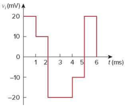
Figure 6.88
For Prob. 6.69.
Sketch the output voltage waveform of an op-amp integrator.
Explanation of Solution
Given data:
The value of the resistor
The value of the capacitor
Refer to Figure 6.88 in the textbook.
Formula used:
Write the expression to calculate the output voltage of an op-amp integrator.
Here,
Calculation:
Substitute
The given input voltage waveform is redrawn as Figure 1.
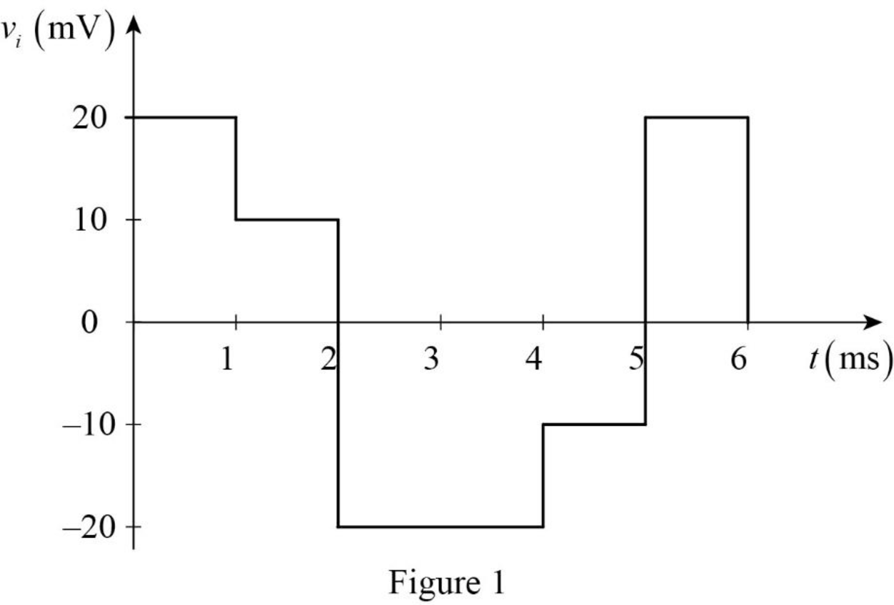
Refer to Figure 1, the input voltage
Case (i): For
Substitute
Simplify the equation to find
Substitute
Case (ii): For
Equation (2) can be rewritten as following equation to find the output voltage for
Substitute
Simplify the equation to find
Substitute
Case (iii): For
Equation (2) can be rewritten as following equation to find the output voltage for
Substitute
Simplify the equation to find
Substitute
Case (iv): For
Equation (2) can be rewritten as following equation to find the output voltage for
Substitute
Simplify the equation to find
Substitute
Case (v): For
Equation (2) can be rewritten as following equation to find the output voltage for
Substitute
Simplify the equation to find
Substitute
Therefore, the output voltage function for Figure 1 is expressed as,
The output voltage waveform is drawn as Figure 2.
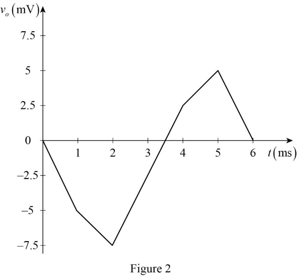
Conclusion:
Thus, the output voltage waveform of an op-amp integrator is sketched.
Want to see more full solutions like this?
Chapter 6 Solutions
FUNDAMENTALS OF ELEC.CIRC.(LL)-W/ACCESS


- Three capacitors 3 µF, 5µF, and 9µF are connected in parallel with an 9V battery. Determine the: (5) energy stored in each capacitor.arrow_forwardThe current I(t) through a 5.0-mH inductor varies with time, as shown below. The resistance of the inductor is 5.0 Ω. Calculate the voltage across the inductor at t = 2.0 ms, t = 4.0 ms, and t = 8.0 ms .arrow_forwardAn op amp has a GBP of 106 . A 0.3 μV sinusoidal signal at 5 KHz is required to beamplified to 5 V. Calculate the gains and draw the schematic circuit to achieve this.arrow_forward
- A 50 Hz, 200 Vpeak voltage source supplies power to a load consisting of a resistor in parallel with a capacitor.The active power delivered by the source is 500 W and the apparent power is 800 VA. Calculate the value of the capacitor in micro-Farad.arrow_forwardThree capacitors connected in a series having the capacitance of 4 mF, 10 mF, and 12 mF. What will be equivalent capacitance in (mF).arrow_forward6.35 An inductor has a linear change in current from50 mA to 100 mA in 2 ms and induces a voltage of160 mV. Calculate the value of the inductorarrow_forward
- . A capacitor has a charge of 20.5 C when connected with a 24V battery. Determine the capacitance.arrow_forwardDesign a monostable multivibrator to have a pulsewidth of 20 s and a recovery time of 5 s. Usethe circuit with ±5 V supplies.arrow_forwardGive reason : a) The total resistance in a circuit with parallel resistors increases , if one of the parallel resistors opens . b) If the inductor is charged it acts as an open circuit. c) If the capacitor is fully discharged it acts as a short circuit .arrow_forward
- SOLVE STEP BY STEP IN DIGITAL FORMAT A 12 volt battery is connected to a series circuit in which the inductor is 1/4 Henry and the resistance is 25 Ohm. Determine the current i, if the initial current is zero.arrow_forwardThe current in a 0.6 microfarad capacitor is 0 [A] for time less than zero and 3cos50000t [A] for time greater than or equal to zero. Find v(t) and the maximum power delivered to the capacitor.arrow_forwardPlease explain this circuit because I still don't understand, this circuit is used for an experiment to calculate SR (Slew Rate) on the op amparrow_forward
 Introductory Circuit Analysis (13th Edition)Electrical EngineeringISBN:9780133923605Author:Robert L. BoylestadPublisher:PEARSON
 Delmar's Standard Textbook Of ElectricityElectrical EngineeringISBN:9781337900348Author:Stephen L. HermanPublisher:Cengage Learning
 Programmable Logic ControllersElectrical EngineeringISBN:9780073373843Author:Frank D. PetruzellaPublisher:McGraw-Hill Education
 Fundamentals of Electric CircuitsElectrical EngineeringISBN:9780078028229Author:Charles K Alexander, Matthew SadikuPublisher:McGraw-Hill Education
 Electric Circuits. (11th Edition)Electrical EngineeringISBN:9780134746968Author:James W. Nilsson, Susan RiedelPublisher:PEARSON
 Engineering ElectromagneticsElectrical EngineeringISBN:9780078028151Author:Hayt, William H. (william Hart), Jr, BUCK, John A.Publisher:Mcgraw-hill Education,