
Concept explainers
Videos
The voltage waveform in Fig. 6.46 is applied across a 55-μF capacitor. Draw the current waveform through it.
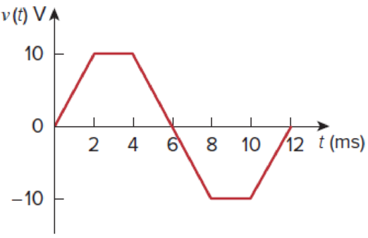
Figure 6.46
For Prob. 6.6.
Find the current waveform.
Explanation of Solution
Given data:
The value of the capacitor
Formula used:
Write the expression to calculate the straight line equation for two points
Refer to Figure 6.46 in the textbook.
From the given graph, substitute
Write the expression to calculate the current through the inductor.
Here,
Calculation:
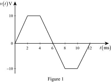
The given voltage waveform is redrawn as Figure 1.
Refer to Figure 1, split up the time period as five divisions such as
Case (i):
The two points
Substitute
Simplify the equation to find
Case (ii):
The two points
Substitute
Simplify the equation to find
Case (iii):
The two points
Substitute
Simplify the equation to find
Case (iv):
The two points
Substitute
Simplify the equation to find
Case (v):
The two points
Substitute
Simplify the equation to find
Therefore, the voltage function of the signal in Figure 1 is,
For
Substitute
Simplify the equation to find
For
Substitute
For
Substitute
Simplify the equation to find
For
Substitute
For
Substitute
Simplify the equation to find
Therefore, the current function of the signal in Figure 1 is,
From the current expression
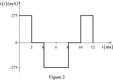
Conclusion:
Thus, the current equation is found and its respective waveform is drawn.
Want to see more full solutions like this?
Chapter 6 Solutions
EBK FUNDAMENTALS OF ELECTRIC CIRCUITS
Additional Engineering Textbook Solutions
Electronics Fundamentals: Circuits, Devices & Applications
Basic Engineering Circuit Analysis
Engineering Electromagnetics
ELECTRICITY FOR TRADES (LOOSELEAF)
Principles and Applications of Electrical Engineering
Electric Circuits. (11th Edition)


- The R-L Circuit: An inductor with an inductance of 2.50 H and a resistance of 7.00 n is connected to the terminals ofa battery with an emf of 6.00 V and an internal resistance of 1.00 n. What is the rate ofincrease of current at the instant when the current is 0.500 A? A) 0.8 A/s B) 0.6 A/s C) 0.4 A/s D) zero E) None of the above.arrow_forwardCalculate the equivalent inductance of the circuit if the 6-mH inductor and the combination of 8-mH and 10-mH inductors in parallel (no coupling between them) are series opposing at 40% coupling.* O 1.7mH O 2.07mH O 7.07mH O 8.37mHarrow_forwardAn inductor in series with a 5 uF capacitor is connected to a supply of 20v , 796Hz. What is the inductance needed to make the current 5A leading?arrow_forward
- Which of the following statement is false O A capacitor cannot store energy if the current through the capacitor is zero. The current flows through an inductor cannot be changed in zero time. O The voltage across a capacitor cannot be changed in zero time. An inductor is a short circuit to DC.arrow_forwardTwo capacitor 6uf and 3uf are connected in series in an emf supply 400v. Calculate The potential difference across each capacitorarrow_forwardA 100 μF capacitor initially charged to 24 V is discharge across a series combination of a 1 kΩ resistor and a 200 μF capacitor. Find the current after 1 sec.arrow_forward
- 5. A series combination of an 18.0 mF capacitor and a resistor are connected to a 125 V battery. After three seconds, the voltage across the capacitor is 49.5 V. (a) What is the resistance of the resistor? (b) If at that three second mark the battery is subsequently removed and the capacitor is allowed to discharge through the resistor then how many excess electrons will remain on the capacitor at the five second mark?arrow_forwardA fully charged capacitor has a voltage of 100V and is then discharged through a resistor. The potential difference across the capacitor is 1V after 10 seconds. What is the time constant of the circuit?arrow_forwardCan the voltage waveform in Fig. 6.42 be associated with a real capacitor?arrow_forward
- > 4. A 50-mH inductor is connected in parallel with a 30-mH inductor. How much inductance must be connected in parallel with this combination if the total inductance is to be 0.01-H? 139arrow_forwardPractice Problem Find the voltage across each of the capacitors in Fig. 6.20. 40 pF 60 uF 90 V 20 uF 30 uF Figure 6.20 30 V.arrow_forward6.54 Find the equivalent inductance looking into the terminals of the circuit in Fig. 6.76. 9 H ll 10H 12 H 4H 6H aarrow_forward
 Delmar's Standard Textbook Of ElectricityElectrical EngineeringISBN:9781337900348Author:Stephen L. HermanPublisher:Cengage Learning