
Videos
Water flows steadily through a splitter as shown in Fig. P6−97 with
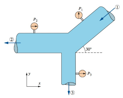
FIGURE P6−97
The external force needed to hold the device fixed.
Answer to Problem 97P
The final resultant force
Explanation of Solution
Given information:
The pressure at pipe
The following figure represents the water flows steadily through a splitter.
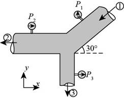
Figure (1)
Write the expression for the cross-sectional area of pipe
Here, the area of pipe
Write the expression for the cross-sectional area of pipe
Here, the area of pipe
Write the expression for the cross-sectional area of pipe
Here, the area of pipe
Write the expression for the velocity of flow in the pipe
Here, the velocity of flow in the pipe
Write the expression for the velocity of flow in the pipe
Here, the velocity of flow in the pipe
Write the expression for the velocity of flow in the pipe
Here, the velocity of flow in pipe
Write the expression for resultant force for
Here, the resultant force foe
Write the expression for resultant force for
Here, the resultant force for
Write the expression for net resultant force.
Here, the net resultant force is
Write the expression for angle of application of force.
Here, the angle of application is
Calculation:
Substitute
Substitute
Substitute
Substitute
Substitute
Substitute
Substitute
Substitute
Substitute
Thus, the final resultant force is
Substitute
The final resultant force
Conclusion:
The final resultant force
Want to see more full solutions like this?
Chapter 6 Solutions
FLUID MECHANICS:FUND.+APPL.(LL)>CUSTOM<


- Water at four-degree Celsius flows through a pipe that has a conical shape and is sloping downward; has a height difference of 20 meters. The cross section at the bottom is one-half that at the top. If the speed and pressure of water at the top are 1 m/s and 3x10⁵ Pa, what is the pressure at the bottom (20 meters below the top)?arrow_forwardA single-stage axial flow pump with outer radius r2 =0.240 m and inner radius r1 =0.120 m is given. At a radius of r =0.090 m, absolute flow flows in from the axial direction just before the impeller inlet and relative flow flows out in the axial direction just after the impeller outlet. Assuming a flow rate Q = 0.265 m^3/s, a water density ρ = 1.000 × 10³ kg/m^3, a rotation speed n = 2.4 × 10^3 rpm, and a gravitational acceleration g = 9.81 m/s^2 , and assuming that the theoretical head Hth = W/g (W: specific work) derived from Euler's law is constant at all impeller radii, answer the following questions. (1) Find the velocity triangles just before the impeller inlet and just after the impeller outlet at a radius of r =0.09 m.arrow_forwardAir at 40°C flow steadily through the pipe shown in Fig. 1 below. If P1 = 40 kPa (gage), P2 = 10 kPa (gage), D = 3d, Patm ≅ 100 kPa, the average velocity at section 2 is V2 = 25 m/s, and air temperature remains nearly constant, determine the average speed at section 1.arrow_forward
- A Francis radial-flow hydroturbine has the following dimensions, where location 2 is the inlet and location 1 is the outlet: r2 = 6.60 ft, r1 = 4.40 ft, b2 = 2.60 ft, and b1 = 7.20 ft. The runner blade angles are ?2 = 82° and ?1 = 46° at the turbine inlet and outlet, respectively. The runner rotates at n. = 120 rpm. The volume flow rate at design conditions is 4.70 ×10⁶ gpm. Irreversible losses are neglected in this preliminary analysis. Calculate the angle ?2 through which the wicket gates should turn the flow, where ?2 is measured from the radial direction at the runner inlet. Calculate the swirl angle ?1, where ?1 is measured from the radial direction at the runner outlet. Does this turbine have forward or reverse swirl? Predict the power output (hp) and required net head (ft).arrow_forwardBetween two sections in a vessel, a fluid moves in a steady flow manner. At entrance: A1=20 m2, ρ1=1300 kgm/m3. At exit: A2=10 m2, ʋ2=0.00125 m3/kg, ῡ2=3 m/min. Determine the following: a) ḿ1 in kg/min b) ῡ1 in m/minarrow_forwarda=2 , b=1 The properties of the air in the inlet section with A1 = 0.25ab m2 in a converging-diverging channel are given as U1 = 25a,b m/s, T1 = 3ab K, P1 = 13a,b kPa (absolute). Find the required cross-sectional area, pressure, temperature, velocity and mass flow rate to obtain sonic (Ma2=1.0) flow at the outlet. Calculate critical values of A*, U*, T*, P*. Solve the problem by making the necessary assumptions and drawing the schematic figure.arrow_forward
- Look up the word affinity in a dictionary. Why do you suppose some engineers refer to the turbomachinery scaling laws as affinity laws?arrow_forwardA fan draws 1.42m3 per second of air at a static pressure of 2.54 cm of water through a duct 300 mm diameter and discharges it through a duct of 275 mm diameter. Determine the static fan efficiency if total fan is 75% and air is measured at 25 degree celsius and 760 mm Hg.arrow_forwardThe water is flowing through a pipe having diameters 40 cm and 21 cm at sections land 2 respectively. The rate of flow through pipe is 45 litres/s. The section 1 is7 m above datum and section 2 is 4.5 m above datum. If the pressure at section 1 is 35 N/cm2. find the following by neglecting losses: (1) Area of cross section of section1(unit in m^2)? 2)Area of cross section of section2 (unit in m^2)? 3)velocity head at section 1 (unit in m) 4)velocity head at section 2 (unit in m) ? 5) difference in datum head (Unit in m)? 6) Pressure head at section 1 (Unit in m)? 7)pressure at section 2 (unit in N/m)?arrow_forward
- An ideal gas flows adiabatically through a duct. At section1, p1 =140 kPa, T1 = 2608C, and V1 = 75 m/s. Fartherdownstream, p2 = 30 kPa and T2 = 2078C. Calculate V2 inm/s and s2 - s1 in J/(kg ? K) if the gas is (a) air, k = 1.4,and (b) argon, k = 1.67. Solve Prob. if the gas is steam. Use two approaches:(a) an ideal gas from Table A.4 and (b) real gas data fromthe steam tablesarrow_forwardA Liquid fluid with a density of 1,750 kg/m3 from an elevated 2m open reservoir (P1=0 bars) flows before the pump at 7.5 m/s. The liquid fluid is pumped at an unknown final velocity to a 75 meter elevated tank with a pressure reading of 7.75 Bars. assuming Friction losses is 757.75J and the actual WORK of the pump is 1,933,400J. Calculate the power in HP if the pump's efficiency is just 75% and for every 1,000 kg of fluid per hour.arrow_forwardAir (? = 1.225 kg/m3 and ? = 1.789 × 10⁻⁵ kg/m⋅s) flows in a wind tunnel, and the wind tunnel speed is measured with a Pitot-static probe. For a certain run, the stagnation pressure is measured to be 560.4 Pa gage and the static pressure is 12.7 Pa gage. Calculate the wind-tunnel speed.arrow_forward
 Elements Of ElectromagneticsMechanical EngineeringISBN:9780190698614Author:Sadiku, Matthew N. O.Publisher:Oxford University Press
 Mechanics of Materials (10th Edition)Mechanical EngineeringISBN:9780134319650Author:Russell C. HibbelerPublisher:PEARSON
 Thermodynamics: An Engineering ApproachMechanical EngineeringISBN:9781259822674Author:Yunus A. Cengel Dr., Michael A. BolesPublisher:McGraw-Hill Education
 Control Systems EngineeringMechanical EngineeringISBN:9781118170519Author:Norman S. NisePublisher:WILEY
 Mechanics of Materials (MindTap Course List)Mechanical EngineeringISBN:9781337093347Author:Barry J. Goodno, James M. GerePublisher:Cengage Learning
 Engineering Mechanics: StaticsMechanical EngineeringISBN:9781118807330Author:James L. Meriam, L. G. Kraige, J. N. BoltonPublisher:WILEY