
Concept explainers
Videos
The truss shown consists of nine members and is supported by a ball and socket at A, two short links at B, and a short link at C. Determine the force in each of the members for the given loading.

The force in each of the members of the truss for the given loading.
Answer to Problem 6.38P
The force in member
Explanation of Solution
The free-body diagram of the entire truss is shown in figure 1.
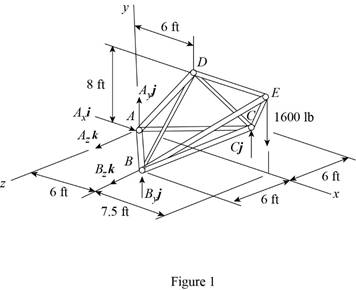
Refer to figure 1 and use symmetry.
Here,
The
Here,
Sum of the moments must be equal to zero.
Here,
Write the equation for
Here,
Put the above equation in equation (I).
Write the expression for the reaction at the point A.
Here,
Substitute
Use symmetry.
Here,
The
Here,
Write the expression for
Put the above equation in equation (II).
Write the expression for the reaction at the point A.
Here,
Substitute
Consider the free body
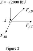
The net force must be equal to zero.
Here,
Write the expression for
Put the above equation in equation (III).
Here,
Write the expression for
Here,
Write the expression for
Here,
Write the expression for
Here,
Put equations (V), (VI) and (VII) in equation (IV).
Factorize
Equate the coefficient of
Equate the coefficient of
Equate the coefficient of
Put equation (X) in equation (IX).
Substitute
Put the above equation in equation (X).
Consider the free-body joint B. The free-body diagram of joint B is shown in figure 3.
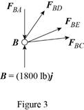
Refer to figure (3) and write the expression for the forces.
Here,
Substitute
Write the expression for
Here,
Write the expression for
Here,
Write the expression for
Here,
Substitute
Write the expression for
Put the above equation in equation (III).
Put equations (XI), (XII), (XIII) , (XIV) and substitute
Equate the coefficient of
Equate the coefficient of
Substitute
Equate the coefficient of
Substitute
Use symmetry.
Here,
Substitute
Consider the free body joint D. The free body diagram is shown in figure 4.
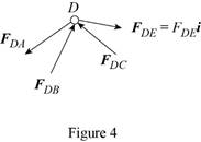
Write the expression for
Put the above equation in equation (III).
Only
Equate the coefficient of
Substitute
Conclusion:
Thus, the force in member
Want to see more full solutions like this?
Chapter 6 Solutions
VECTOR MECH...,STAT.+DYNA.(LL)-W/ACCESS


- THE TRUSS SHOWN CONSISTS OF SIX MEMBERS AND IS SUPPORTED BY A SHORT LINK AT A, TWO SHORT LINKS AT B, AND A BALL-AND-SOCKET AT D. DETERMINE THE FORCE IN EACH OF THE MEMBERS FOR THE GIVEN LOADING. INDICATE WHETHER IN TENSION OR COMPRESSION. -7 ft- -7 ft- 10 ft B O 24 ft 500 lbarrow_forwardFind the magnitude and nature of the forces in all the members of the given truss. Figure: 3aand 3barrow_forwardFor The Truss Shown, Use The Method Of Sections To Find The Internal Forces For Bars BC, BG, And FGarrow_forward
- 3. Given the truss shown below, determine the force in members CD, CE, BE, CB and AB and state whether the members are in tension or compression. 500 Ib 500 lb - 3 ft-3 ft- -3 ft- 6 ft 800 lb BO 6 ft A -9 ftarrow_forwardProblem 1: Calculate the forces in the required members of the truss shown: F1 F2 F3 H F h F4 C D E 4 @ S Given: F1 = 14 kN F2 = 14 kN F3 = 12 kN F4 = 16 kNarrow_forwardDetermine (approximately) the forces in each truss member and column of the portal frame. Assume all members of the truss and columns to be pin connected at their ends. (Provide complete solution, summary of results) 6 ft F 6 ft 4k D E H 3 ft 12 ft Font sa- -8 ft-8 ft--8 ft--8 ft-arrow_forward
- Please help me identify the zero force members in this truss.arrow_forwardSolve the following problems by the method of sections. State whether the members are in tension or compression. Determine the forces in members BC, BF, and EF of the truss shown in Fig. B 4 m E F G 3 m -3 m 3 m 5 kN 3 kNarrow_forwardDetermine the force in bars BD, CD and DE of the nacelle truss shown in figure.arrow_forward
- Identify the zero force members in the following truss.arrow_forwardThe truss carries the loads as shown in Figure 2. The truss is supported by pin at A and smoothroller support at G. (b)By using method of section, determine the force in members CD, CJ and KJ of the truss.State if the members are in tension or compression.arrow_forwardFor the given loading, determine the zero-force members in the truss shown.arrow_forward
 International Edition---engineering Mechanics: St...Mechanical EngineeringISBN:9781305501607Author:Andrew Pytel And Jaan KiusalaasPublisher:CENGAGE L