
Concept explainers
Videos
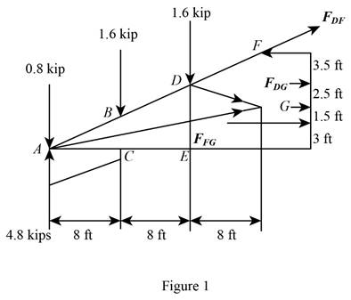
A Howe scissors roof truss is loaded as shown. Determine force in members DF, DG, and EG.
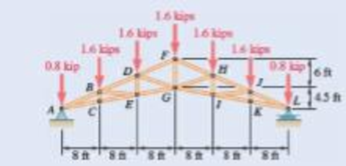
Fig. P6.57 and P6.58
The force in the members
Answer to Problem 6.57P
The force in the members
Explanation of Solution
The Howe scissors roof truss is loaded as shown in the figure. There is load at all the point on the top. The free body diagram of the given arrangement is given by Figure 1.
The total load on the truss is given from the figure as,
By symmetry the
From the diagram the sum of the moments in the counter clockwise direction about
From the diagram the sum of the moments in the counter clockwise direction about
From the diagram the sum of the moments in the counter clockwise direction about
Conclusion:
Solve for
Solve for
Solve for
Therefore, the force in the members
Want to see more full solutions like this?
Chapter 6 Solutions
VECTOR MECH...,STAT.+DYNA.(LL)-W/ACCESS
Additional Engineering Textbook Solutions
Fundamentals of Aerodynamics
Engineering Mechanics: Statics & Dynamics (14th Edition)
Vector Mechanics For Engineers
Machine Elements in Mechanical Design (6th Edition) (What's New in Trades & Technology)
Shigley's Mechanical Engineering Design (McGraw-Hill Series in Mechanical Engineering)


- (3) Using the method of sections, determine the force in member CG and state whether it is in tension or compression. 1.5 m, 1.5 m, 1.5 m. 1.5 m, 1.5 m, 1.5 m 2 kN 2 kN 12 kN 2 kN 1 kN 2 kN 1 kN F. H. 2 m Fig. P6.10arrow_forward1. Using the method of joints. determine the force in members AD, BD and CD of the truss shown in Fig. (a). Indicate whether the members are in tension or compression. 10 kN L. 6 m 3 m 3 m A D 60 kNarrow_forwardSolve Prob. 6.24 assuming that the cables hanging from the right side of the tower have fallen to the ground.(Reference to Problem 6.24):The portion of truss shown represents the upper part of a power transmission line tower. For the given loading, determine the force in each of the members located above HJ . State whether each member is in tension or compression.arrow_forward
- 6.42 A floor truss is loaded as shown. Determine the force in 250 lb 500 lb 500 lb 375 lb 250 |b 250 |b 125 ||. 4 ft 4 ft bers CF, EF, and EG. 4 ft 4 ft 4 ft 4 ft E GV B. 2 ft Fig. P6.42 and P6.43arrow_forward-2 m -2 m – 4.5 kN 1.4 kN E 2.8 kN Do G 0.5 m F 1 kN I kN B 3 m I kN. I kN A |C I 1 m '1m 1 m 1 m Fig. P6.15 and P6.16 6.16 For the Gambrel roof truss shown, determine the force in members CG and CI and in each of the members located to the right of the centerline of the truss. State whether each member is in tension or compression.arrow_forward6.1 through 6.8 Using the method of joints, determine the force in each member of the truss shown. State whether ch member is in tension or compression. 375 lb A 8 ft 500 lb В C O D 8.4 ft Fig. P6.4arrow_forward
- 6.1 through 6.8 Using the method of joints, determine the force in each member of the truss shown, State whether each member is in tension or compression. 48 kN 3 m 4 m 1.25 m 300 Ib Ao 4 m 3.2 m 20 in. 84 kN 48 in. 3 m- 15 in. Fig. P6.1 Fig. P6.2 Fig. P6.3arrow_forwardSolve Prob. 6.39 for P = 0 and Q = (-900 N)k.(Reference to Problem 6.39):The truss shown consists of nine members and is supported by a ball-and-socket at B , a short link at C , and two short links at D. (a) Check that this truss is a simple truss, that it is completely constrained, and that the reactions at its supports are statically determinate. (b) Determine the force in each member for P= (-1200 N)j and Q = 0.arrow_forwardProblem 1: Determine the forces in all bars of the truss shown. Indicate whether the bars are in tension or compression.arrow_forward
- Using the method of joint. Determine the force in each member of the truss shown in Fig. 5. Also, state if the members are in tension or compression. 4 kN 3 m -3 m 3 m B D 3 m 5 m 5 kN Fig. 5arrow_forward6.1 through 6.8 Using the method of joints, determine the force in each member of the truss shown. State whether each member is in tension or compression.arrow_forward6.53 A Pratt roof truss is loaded as shown. Determine the force in members CE, DE, and DF. 3 kN 3 kN 3 kN F 3 kN 3 kN H. 1.5 kN 16.75 m 1.5 kN В E K 3 m 3 m 3 m 3 m 3 m 3 marrow_forward
 Elements Of ElectromagneticsMechanical EngineeringISBN:9780190698614Author:Sadiku, Matthew N. O.Publisher:Oxford University Press
 Mechanics of Materials (10th Edition)Mechanical EngineeringISBN:9780134319650Author:Russell C. HibbelerPublisher:PEARSON
 Thermodynamics: An Engineering ApproachMechanical EngineeringISBN:9781259822674Author:Yunus A. Cengel Dr., Michael A. BolesPublisher:McGraw-Hill Education
 Control Systems EngineeringMechanical EngineeringISBN:9781118170519Author:Norman S. NisePublisher:WILEY
 Mechanics of Materials (MindTap Course List)Mechanical EngineeringISBN:9781337093347Author:Barry J. Goodno, James M. GerePublisher:Cengage Learning
 Engineering Mechanics: StaticsMechanical EngineeringISBN:9781118807330Author:James L. Meriam, L. G. Kraige, J. N. BoltonPublisher:WILEY