
Concept explainers
Videos
The truss shown consists of nine members and is support by a ball-and-socket at B, a short link at C, and two short links at D. (a) Check that this truss is a simple truss, that completely constrained, and that the reactions at its suppo are statically determinate. (b) Determine the force in each member for P = (−1200 N)j and Q = 0.
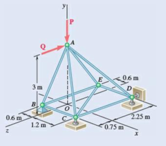
Fig. P6.39
(a)
Verify that the truss is a simple truss, completely constrained, and the reactions at the supports are statically determinate.
Answer to Problem 6.39P
The reactions at supports B, C, and D is
Explanation of Solution
Given information:
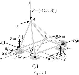
The value of the force P is
The value of the force Q is zero.
Calculation:
Show the free-body diagram of the truss as in Figure 1.
Find the vector coordinates by taking moment about point B.
Equate the coefficients of i to zero.
Equate the coefficients of j to zero.
Equate the coefficients of k to zero.
Substitute 300 N for
Resolve the force components in y-axis.
Substitute 300 N for
The unknown reactions can be calculated with the equilibrium equations. Therefore, the truss is statically determinate, completely constrained and simple truss.
Thus, the reactions at supports B, C, and D is
(b)
Find the force in each member of the truss.
Answer to Problem 6.39P
The force in the member AB is
The force in the member BC is
The force in the member BE is
The force in the member AC is
The force in the member CE is
The force in the member CD is
The force in the member AD is
The force in the member DE is
The force in the member AE is
Explanation of Solution
Show the free-body diagram of the joint B as in Figure 2.
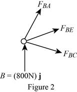
Resolve the force components as follows;
Write the vector value of
Find the scalar quantity of BA using the relation.
Find the force in the member AB as follows;
Substitute
Find the force in the member BC as follows;
Find the force in the member BE as follows;
Equate the coefficients of j to zero.
Equate the coefficients of i to zero.
Substitute –840 N for
Equate the coefficients of k to zero.
Substitute –840 N for
Therefore,
The force in the member AB is
The force in the member BC is
The force in the member BE is
Show the free-body diagram of the joint C as in Figure 3.
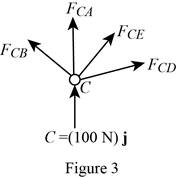
Resolve the force components as follows;
Write the vector value of
Find the scalar quantity of CA using the relation.
Find the force in the member AC as follows;
Substitute
Find the force in the member CB as follows;
Find the force in the member CD as follows;
Write the vector value of
Find the scalar quantity of CE using the relation.
Find the force in the member CE as follows;
Substitute
Equate the coefficients of j to zero.
Equate the coefficients of i to zero.
Substitute –110.6 N for
Equate the coefficients of k to zero.
Substitute –110.6 N for
Therefore,
The force in the member AC is
The force in the member CE is
The force in the member CD is
Show the free-body diagram of the joint D as in Figure 4.
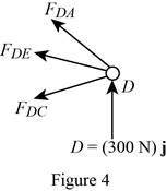
Resolve the force components as follows;
Write the vector value of
Find the scalar quantity of DA using the relation.
Find the force in the member AD as follows;
Substitute
Find the force in the member DC as follows;
Find the force in the member DE as follows;
Equate the coefficients of j to zero.
Equate the coefficients of i to zero.
Substitute –394 N for
Therefore,
The force in the member AD is
The force in the member DE is
Show the free-body diagram of the joint E as in figure 5.
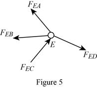
The member AE is not in the xz plane.
Therefore, the force in the member AE is
Want to see more full solutions like this?
Chapter 6 Solutions
Vector Mechanics for Engineers: Statics and Dynamics


- The T-shaped bracket shown is supported by a small wheel at E and pegs at C and D . Neglecting the effect of friction, determine the reactions at C, D, and E when 0= 30°.arrow_forwardMember ABC is supported by a pin and bracket at B and by an inextensible cord attached at A and C and passing over a frictionless pulley at D. The tension may be assumed to be the same in portions AD and CD of the cord. For the loading shown and neglecting the size of the pulley, determine the tension in the cord and the reaction at B.arrow_forwardA 48-in. boom is held by a ball-and-socket joint at C and by two cables BF and DAE; cable DAE passes around a frictionless pulley at A. For the loading shown, determine the tension in each cable and the reaction at C.arrow_forward
- The L-shaped member ACB is supported by a pin and bracket at C and by an inextensible cord attached at A and B and passing over a frictionless pulley at D. The tension may be assumed to be the same in portions AD and BD of the cord. If the magnitudes of the forces applied at A and B are, respectively, P = 25 lb and Q = 0, determine (a) the tension in the cord, (b) the reaction at Carrow_forwardSolve Prob. 4.140, subject to the restriction that H must lie on the y axis.(Reference to Problem 4.140):Two 2 × 4-ft plywood panels, each with a weight of 12 lb, are nailed together as shown. The panels are supported by ball-and-socket joints at A and F and by the wire BH . Determine (a) the location of H in the xy plane if the tension in the wire is to be minimum, (b) the corresponding minimum tension.arrow_forwardDetermine the force in member DE and in each of the members located to the left of DE for the inverted Howe roof truss shown. State whether each member is in tension or compression. Fig. P6. 17arrow_forward
- Solve Prob. 4.19, assuming that a= 0.32 m.(Reference to Problem 4.19):The bracket BCD is hinged at C and attached to a control cable at B . For the loading shown, determine (a) the tension in the cable, (b) the reaction at C.arrow_forwardA vertical bar AD is attached to two springs of constant k and is in equilibrium in the position shown. Determine the range of values of the magnitude P of two equal and opposite vertical forces P and -P for which the equilibrium position is stable if (a) AB= CD, (b) AB = 2CD.arrow_forwardSolve Prob. 4.133, assuming that cable GBH is replaced by a cable GB attached at G and B.(Reference to Problem 4.133):The frame ACD is supported by ball-and-socket joints at A and D and by a cable that passes through a ring at B and is attached to hooks at G and H . Knowing that the frame supports at point C a load of magnitude P = 268 N, determine the tension in the cable.arrow_forward
- A light bar AD is suspended from a cable BE and supports a 50-lb block at C. The ends A and D of the bar are in contact with frictionless vertical walls. Determine the tension in cable BE and the reactions at A and D.arrow_forwardArm ABC is connected by pins to a collar at B and to crank CD at C Neglecting the effect of friction, determine the couple M required to hold the system in equilibrium 'when 0= 0.Fig.P6.133arrow_forwardA 48-in. boom is held by a ball-and-socket joint at C and by two cables BF and DAF passes around a frictionless pulley at A . For the loading shown, determine the tension in each cable and the reaction at C.arrow_forward
 International Edition---engineering Mechanics: St...Mechanical EngineeringISBN:9781305501607Author:Andrew Pytel And Jaan KiusalaasPublisher:CENGAGE L