
Concept explainers
Videos
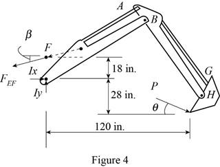
The motion of the backhoe bucket shown is controlled by the hydraulic cylinders AD, CG, and EF. As a result of an attempt to dislodge a portion of a slab, a 2-kip force P is exerted on the bucket teeth at J. Knowing that θ = 45°, determine the force exerted by each cylinder.
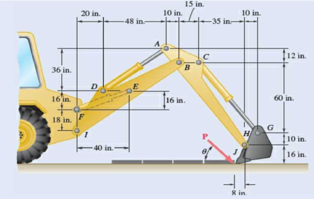
Fig. P6.157
The force exerted by each cylinder shown in figure
Answer to Problem 6.157P
The force exerted by the cylinder
Explanation of Solution
Take all vectors along the
Let P is the force exerted on the bucket at J.
The magnitude of force
The free body diagram of the bucket is sketched below as figure 1.
Here,
Write the expression for the moment at
Here,
Above equation implies that net moment at any point is the sum of product of each force acting on the system and perpendicular distance of the force and the point.
The moment at
Thus, the complete expression of net anticlockwise moment
Here,
At equilibrium, the sum of the moment acting at
Write the expression for the total moment acting at
From figure 1 , write the expression for the
From figure 1 , write the expression for the
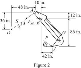
The free body diagram of the bucket and arm
Here,
Write the expression for the moment at
Here,
Above equation implies that net moment at any point is the sum of product of each force acting on the system and perpendicular distance of the force and the point.
The moment at
Thus, the complete expression of net anticlockwise moment
Here,
At equilibrium, the sum of the moment acting at
Write the expression for the total moment acting at
From figure 2 , write the expression for the
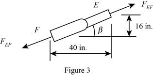
Geometry of cylinder
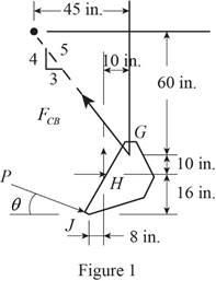
The free body diagram of the bucket and both arms is sketched below as figure 4.
Here,
Write the expression for the moment at
Here,
Above equation implies that net moment at any point is the sum of product of each force acting on the system and perpendicular distance of the force and the point.
The moment at
Thus, the complete expression of net anticlockwise moment
Here,
At equilibrium, the sum of the moment acting at
Write the expression for the total moment acting at
From figure 3 , write the expression for the
Calculation:
Substitute
The negative sign indicate that the cylinder undergoes compression.
Substitute
The negative sign indicate that the cylinder undergoes compression.
Rearrange the equation (X) to get

Substitute
The positive sign indicate that the cylinder
Therefore, the force exerted by the cylinder
Want to see more full solutions like this?
Chapter 6 Solutions
Vector Mechanics for Engineers: Statics and Dynamics


- Knowing that the radius of each pulley is 200 mm and neglecting friction, determine the internal forces at point J of the frame shown.arrow_forwardA single-acting cylinder working in traction under a pressure of60 psig has a return spring with a force of 15 lbs. Knowing that the diameter ofthe rod is ¼ in. and that of the piston is 1 in., what is the force developedby this cylinder? [Answer:29.4 lbs]arrow_forwardA freight car is stopped on a track at an angle of 25o to the vertical. The gross weight of the wagon and its load is 36kN and acts at a point 750 mm from the track, in the middle between the two axles. The wagon is supported by a cable 600 mm from the track. Determine the traction on the cable and the reaction on each pair of wheels.arrow_forward
- The cab and motor units of the front-end loader shown are connected by a vertical pin located 2 m behind the cab wheels. The distance from C to D is 1 m. The center of gravity of the 300-kN motor unit is located at Gm , while the centers of gravity of the 100-kN cab and 75-kN load are located, respectively, at Gc and GI. . Knowing that the machine is at rest with its brakes released, determine (a) the reactions at each of the four wheels, (b) the forces exerted on the motor unit at C and D.arrow_forward4.7 A hand truck is used to move a compressed-air cylinder. Knowing that the combined weight of the truck and cylinder is 180 lb. determine (a) the vertical force P that should be applied to the handle to maintain the cylinder in the position shown, (b) the corresponding reaction at each of the two wheels.arrow_forwardA freight wagon is at rest on a track at an angle of 25o to the vertical. The gross weight of the wagon and its load is 36kN and acts at a point 750 mm from the track, in the middle between the two axles. The wagon is held by a cable 600 mm from the track. Determine the traction on the cable and the reaction on each pair of wheels.arrow_forward
- Knowing that the radius of each pulley is 150 mm, that a = 20°, and neglecting friction, determine the internal forces at (a) point J, (b) point K.arrow_forwardTwo transmission belts pass over a double-sheaved pulley that is attached to an axle supported by bearings at A and D . The radius of the inner sheave is 125 mm and the radius of the outer sheave is 250 mm. Knowing that when the system is at rest, the tension is 90 N in both portions of belt B and 150 N in both portions of belt C , determine the reactions at A and D . Assume that the bearing at D does not exert any axial thrust.arrow_forwardFor the cables of Prob. 2.46, it is known that the maximum allowable tension is 600 N in cable AC and 750 N in cable BC . Determine (a) the maximum force P that can be applied at C, (b) the corresponding value of a.(Reference to Problem 2.46):Two cables are tied together at C and are loaded as shown. Knowing that P = 500 N and a = 60°, determine the tension in (a) in cable AC, (b) in cable BC.arrow_forward
- A steam pipe weighing 45 lb/ft that passes between two buildings 40 ft apart is supported by a system of cables as shown. Assuming that the weight of the cable system is equivalent to a uniformly distributed loading of 5 lb/ft, determine (a) the location of the lowest point C of the cable, (b) the maximum tension in the cable.arrow_forwardThe bucket of the front-end loader shown carries a 3200-lb load. The motion of the bucket is controlled by two identical mechanisms, only one of which is shown. Knowing that the mechanism shown supports one-half of the 3200-lb load, determine the force exerted (a) by cylinder CD, (b) by cylinder FH.arrow_forwardTwo forces P and Q are applied as shown to an aircraft connection. Knowing that the connection is in equilibrium and that P=500 lb and Q = 650 lb, determine the magnitudes of the forces exerted on the rods A and B.arrow_forward
 Elements Of ElectromagneticsMechanical EngineeringISBN:9780190698614Author:Sadiku, Matthew N. O.Publisher:Oxford University Press
 Mechanics of Materials (10th Edition)Mechanical EngineeringISBN:9780134319650Author:Russell C. HibbelerPublisher:PEARSON
 Thermodynamics: An Engineering ApproachMechanical EngineeringISBN:9781259822674Author:Yunus A. Cengel Dr., Michael A. BolesPublisher:McGraw-Hill Education
 Control Systems EngineeringMechanical EngineeringISBN:9781118170519Author:Norman S. NisePublisher:WILEY
 Mechanics of Materials (MindTap Course List)Mechanical EngineeringISBN:9781337093347Author:Barry J. Goodno, James M. GerePublisher:Cengage Learning
 Engineering Mechanics: StaticsMechanical EngineeringISBN:9781118807330Author:James L. Meriam, L. G. Kraige, J. N. BoltonPublisher:WILEY