Vector Mechanics for Engineers: Statics and Dynamics
12th Edition
ISBN: 9781259638091
Author: Ferdinand P. Beer, E. Russell Johnston Jr., David Mazurek, Phillip J. Cornwell, Brian Self
Publisher: McGraw-Hill Education
bartleby

Videos

Question
Book Icon
Chapter 6.4, Problem 6.158P
To determine

The force exerted by each cylinder shown in figure P6.157 if θ=0° .

Expert Solution & Answer
Check Mark

Answer to Problem 6.158P

The force exerted by the cylinder EF is 3.35kips compression, force exerted by the cylinder AD is 11.03kips compression and the force exerted by the cylinder CG is 2.29kips compression.

Explanation of Solution

Take all vectors along the x axis and y axis as positive.

Let P is the force exerted on the bucket at J.

The magnitude of force P is equal to 2kips and angle that force P makes with x axis equal to, θ=0°.

The free body diagram of the bucket is sketched below as figure 1.
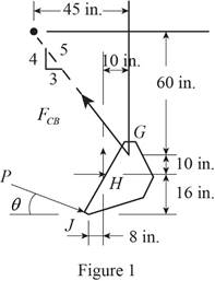
 Vector Mechanics for Engineers: Statics and Dynamics, Chapter 6.4, Problem 6.158P , additional homework tip  1

Here, FCG is the magnitude of force exerted by the cylinder CG on the bucket ,H is the joint about which bucket rotate and α is the angle that direction of force FCG makes with y axis.

Write the expression for the moment at H

MH=F×D (I)

Here, MH is the net moment at H, F is the force, and D is the perpendicular distance between the H and the point where force is experienced.

Above equation implies that net moment at any point is the sum of product of each force acting on the system and perpendicular distance of the force and the point.

The moment at H is due to the x and y component of force FCG and sine and cosine component of force P.

Thus, the complete expression of net anticlockwise moment MH at point H.

MH=FCGcosα(10in.)+FCGsinα(10in.)+Pcosθ(16in.)+Psinθ(8in.)=0 (II)

Here, MH is the sum of all moment of force at H.

At equilibrium, the sum of the moment acting at H will be zero.

Write the expression for the total moment acting at H.

MH=FCGcosα(10in.)+FCGsinα(10in.)+Pcosθ(16in.)+Psinθ(8in.)=0 (III)

From figure 1 , write the expression for the cosα.

cosα=45

From figure 1 , write the expression for the sinα.

sinα=35

The free body diagram of the bucket and arm
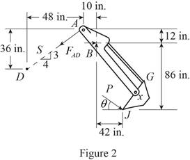
 ABH is sketched below as figure 2.

Vector Mechanics for Engineers: Statics and Dynamics, Chapter 6.4, Problem 6.158P , additional homework tip  2

Here, FAD is the magnitude of force exerted by the cylinder AD on the arm AH ,B is the joint about which the arm AH rotate and β is the angle that direction of force FAD makes with x axis.

Write the expression for the moment at B

MB=F×D (IV)

Here, MB is the net moment at J, F is the force, and D is the perpendicular distance between the B and the point where force is experienced.

Above equation implies that net moment at any point is the sum of product of each force acting on the system and perpendicular distance of the force and the point.

The moment at B is due to the x component of force FAD , y component of force FAD, sine and cosine component of force P.

Thus, the complete expression of net anticlockwise moment MB at point B.

MB=FADcosβ(12in.)+FADsinβ(10in.)+Pcosθ(86in.)Psinθ(42in.)=0 (V)

Here, MB is the sum of all moment of force at B.

At equilibrium, the sum of the moment acting at B will be zero.

Write the expression for the total moment acting at J.

MB=FADcosβ(12in.)+FADsinβ(10in.)+Pcosθ(86in.)Psinθ(42in.)=0 (VI)

From figure 2 , write the expression for the cosβ and sinβ.

cosβ=45

sinβ=35

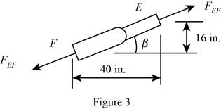
Geometry of cylinder EF is shown in figure 4.

Vector Mechanics for Engineers: Statics and Dynamics, Chapter 6.4, Problem 6.158P , additional homework tip  3

The free body diagram of the bucket and both arms is sketched below as figure 4.
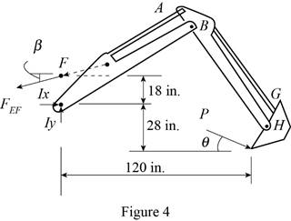
Vector Mechanics for Engineers: Statics and Dynamics, Chapter 6.4, Problem 6.158P , additional homework tip  4

Here, FEF is the magnitude of force exerted by the cylinder EF on the arm BI ,I is the joint about which arm BI rotate and γ is the angle that direction of force FEF makes with x axis.

Write the expression for the moment at I

MI=F×D (VII)

Here, MI is the net moment at I, F is the force, and D is the perpendicular distance between the I and the point where force is experienced.

Above equation implies that net moment at any point is the sum of product of each force acting on the system and perpendicular distance of the force and the point.

The moment at I is due to the x component of force FEF and sine and cosine component of force P.

Thus, the complete expression of net anticlockwise moment MK at point K.

MI=FEFcosγ(18in.)+Pcosθ(28in.)Psinθ(120in.)=0 (VIII)

Here, MI is the sum of all moment of force at I.

At equilibrium, the sum of the moment acting at I will be zero.

Write the expression for the total moment acting at I.

MI=FEFcosγ(18in.)+Pcosθ(28in.)Psinθ(120in.)=0 (IX)

From figure 3 , write the expression for the tanγ

tanγ=16in.40in. (X)

Calculation:

Substitute 45 for cosα , 35 for sinα , 2kips for P and 0° for θ rearrange the equation (III) to get FEF.

FCG(45)(10in.)+FCG(35)(10in.)+Pcos0°(16in.)+Psin0°(8in.)=0

FCG=(2kips)(16in.)+(2kips)(12)(8in.)(45)(10in.)+(35)(10in.)=(2kips)((16in.)+(8in.))(45)(10in.)+(35)(10in.)=2.29kips

The negative sign indicate that the cylinder undergoes compression.

Substitute 45 for cosβ , 35 for sinβ , 2kips for P and 0° for θ rearrange the equation (VI) to get FAD.

FAD(45)(12in.)+FAD(35)(10in.)+(2kips)cos0°(86in.)(2kips)sin0°(42in.)=0

FAD=(2kips)((42in.)(86in.))(45)(12in.)+(35)(10in.)=11.03kips

The negative sign indicate that the cylinder undergoes compression.

Rearrange the equation (X) to get γ .

Vector Mechanics for Engineers: Statics and Dynamics, Chapter 6.4, Problem 6.158P , additional homework tip  5tanγ=16in.40in.γ=21.801°

Substitute 21.801° for γ and 2kips for P and 0° for θ rearrange the equation (IX) to get FEF.

FEFcos(21.801°)(18in.)+(2kips)cos0°(28in.)(2kips)sin0°(120in.)=0

FEF=(2kips)((120in.)(28in.))cos(21.801°)(18in.)=3.35kips

The positive sign indicate that the cylinder EF undergoes compression.

Therefore, the force exerted by the cylinder EF is 3.35kips compression, force exerted by the cylinder AD is 11.03kips compression and the force exerted by the cylinder CG is 2.29kips compression.

Want to see more full solutions like this?

Subscribe now to access step-by-step solutions to millions of textbook problems written by subject matter experts!
Students have asked these similar questions
A freight wagon is at rest on a track at an angle of 25o to the vertical. The gross weight of the wagon and its load is 36kN and acts at a point 750 mm from the track, in the middle between the two axles. The wagon is held by a cable 600 mm from the track. Determine the traction on the cable and the reaction on each pair of wheels.
In order to unscrew the tapped faucet A, a plumber uses two pipe wrenches as shown. By exerting a 40-lb force on each wrench, at a distance of 10 in. from the axis of the pipe and in a direction perpendicular to the pipe and to the wrench, he prevents the pipe from rotating, and thus avoids loosening or further tightening the joint between the pipe and the tapped elbow C. Determine (a) the angle θ that the wrench at A should form with the vertical if elbow C is not to rotate about the vertical, (b) the force-couple system at Cequivalent to the two 40-lb forces when this condition is satisfied.
A freight car is stopped on a track at an angle of 25o to the vertical. The gross weight of the wagon and its load is 36kN and acts at a point 750 mm from the track, in the middle between the two axles. The wagon is supported by a cable 600 mm from the track. Determine the traction on the cable and the reaction on each pair of wheels.

Chapter 6 Solutions

Vector Mechanics for Engineers: Statics and Dynamics

Ch. 6.1 - Determine the force in each member of the Gambrel...Ch. 6.1 - Determine the force in each member of the Howe...Ch. 6.1 - Using the method of joints, determine the force in...Ch. 6.1 - Using the method of joints, determine the force in...Ch. 6.1 - Determine the force in each member of the Warren...Ch. 6.1 - Solve Problem 6.15 assuming that the load applied...Ch. 6.1 - Determine the force in each member of the Pratt...Ch. 6.1 - The truss shown is one of several supporting an...Ch. 6.1 - Determine the force in each member of the Pratt...Ch. 6.1 - Prob. 6.20PCh. 6.1 - Determine the force in each of the members located...Ch. 6.1 - Determine the force in member DE and in each of...Ch. 6.1 - Determine the force in each of the members located...Ch. 6.1 - The portion of truss shown represents the upper...Ch. 6.1 - For the tower and loading of Prob. 6.24 and...Ch. 6.1 - Solve Problem 6.24 assuming that the cables...Ch. 6.1 - Determine the force in each member of the truss...Ch. 6.1 - Determine the force in each member of the truss...Ch. 6.1 - Determine whether the trusses of Problems 6.31a,...Ch. 6.1 - Determine whether the trusses of Problems 6.31b,...Ch. 6.1 - For the given loading, determine the zero-force...Ch. 6.1 - Prob. 6.32PCh. 6.1 - For the given loading, determine the zero-force...Ch. 6.1 - Prob. 6.34PCh. 6.1 - Prob. 6.35PCh. 6.1 - Prob. 6.36PCh. 6.1 - The truss shown consists of six members and is...Ch. 6.1 - The truss shown consists of nine members and is...Ch. 6.1 - The truss shown consists of nine members and is...Ch. 6.1 - Solve Prob. 6.39 for P = 0 and Q = (900 N)k. 6.39...Ch. 6.1 - The truss shown consists of 18 members and is...Ch. 6.1 - The truss shown consists of 18 members and is...Ch. 6.2 - Determine the force in members BD and DE of the...Ch. 6.2 - Determine the force in members DG and EG of the...Ch. 6.2 - Determine the force in members BD and CD of the...Ch. 6.2 - Determine the force in members DF and DG of the...Ch. 6.2 - A floor truss is loaded as shown. Determine the...Ch. 6.2 - A floor truss is loaded as shown. Determine the...Ch. 6.2 - Determine the force in members CD and DF of the...Ch. 6.2 - Determine the force in members CE and EF of the...Ch. 6.2 - Determine the force in members DE and DF of the...Ch. 6.2 - Prob. 6.52PCh. 6.2 - Determine the force in members DF and DE of the...Ch. 6.2 - Prob. 6.54PCh. 6.2 - A Pratt roof truss is loaded as shown. Determine...Ch. 6.2 - A Pratt roof truss is loaded as shown. Determine...Ch. 6.2 - A Howe scissors roof truss is loaded as shown....Ch. 6.2 - A Howe scissors roof truss is loaded as shown....Ch. 6.2 - Determine the force in members AD, CD, and CE of...Ch. 6.2 - Determine the force in members DG, FG, and FH of...Ch. 6.2 - Determine the force in member GJ of the truss...Ch. 6.2 - Determine the force in members DG and FH of the...Ch. 6.2 - Determine the force in members CD and JK of the...Ch. 6.2 - Determine the force in members DE and KL of the...Ch. 6.2 - The diagonal members in the center panels of the...Ch. 6.2 - The diagonal members in the center panels of the...Ch. 6.2 - Prob. 6.67PCh. 6.2 - Prob. 6.68PCh. 6.2 - Classify each of the structures shown as...Ch. 6.2 - Classify each of the structures shown as...Ch. 6.2 - Prob. 6.71PCh. 6.2 - 6.70 through 6.74 classify as determinate or...Ch. 6.2 - 6.70 through 6.74 classify as determinate or...Ch. 6.2 - 6.70 through 6.74 classify as determinate or...Ch. 6.3 - For the frame and loading shown, draw the...Ch. 6.3 - For the frame and loading shown, draw the...Ch. 6.3 - Draw the free-body diagram(s) needed to determine...Ch. 6.3 - Knowing that the pulley has a radius of 0.5 m,...Ch. 6.3 - and 6.76 Determine the force in member BD and the...Ch. 6.3 - and 6.76 Determine the force in member BD and the...Ch. 6.3 - For the frame and loading shown, determine the...Ch. 6.3 - Determine the components of all forces acting on...Ch. 6.3 - The hydraulic cylinder CF, which partially...Ch. 6.3 - The hydraulic cylinder CF, which partially...Ch. 6.3 - Determine the components of all forces acting on...Ch. 6.3 - Determine the components of all forces acting on...Ch. 6.3 - Determine the components of the reactions at A and...Ch. 6.3 - Determine the components of the reactions at D and...Ch. 6.3 - Determine the components of the reactions at A and...Ch. 6.3 - Determine the components of the reactions at A and...Ch. 6.3 - Prob. 6.87PCh. 6.3 - The 48-lb load can be moved along the line of...Ch. 6.3 - The 48-lb load is removed and a 288-lb in....Ch. 6.3 - (a) Show that, when a frame supports a pulley at...Ch. 6.3 - Knowing that each pulley has a radius of 250 mm,...Ch. 6.3 - Knowing that the pulley has a radius of 75 mm,...Ch. 6.3 - Two 9-in.-diameter pipes (pipe 1 and pipe 2) are...Ch. 6.3 - Prob. 6.94PCh. 6.3 - Prob. 6.95PCh. 6.3 - Prob. 6.96PCh. 6.3 - Prob. 6.97PCh. 6.3 - Prob. 6.98PCh. 6.3 - Knowing that P = 90 lb and Q = 60 lb, determine...Ch. 6.3 - Knowing that P = 90 lb and Q = 60 lb, determine...Ch. 6.3 - For the frame and loading shown, determine the...Ch. 6.3 - For the frame and loading shown, determine the...Ch. 6.3 - Knowing that P = 15 lb and Q = 65 lb, determine...Ch. 6.3 - Knowing that P = 25 lb and Q = 55 lb, determine...Ch. 6.3 - For the frame and loading shown, determine the...Ch. 6.3 - Prob. 6.106PCh. 6.3 - The axis of the three-hinge arch ABC is a parabola...Ch. 6.3 - The axis of the three-hinge arch ABC is a parabola...Ch. 6.3 - Prob. 6.109PCh. 6.3 - Prob. 6.110PCh. 6.3 - 6.111, 6.112, and 6.113 Members ABC and CDE are...Ch. 6.3 - Prob. 6.112PCh. 6.3 - 6.111, 6.112, and 6.113 Members ABC and CDE are...Ch. 6.3 - Members ABC and CDE are pin-connected at C and...Ch. 6.3 - Solve Prob. 6.112 assuming that the force P is...Ch. 6.3 - Solve Prob. 6.114 assuming that the force P is...Ch. 6.3 - Prob. 6.117PCh. 6.3 - Prob. 6.118PCh. 6.3 - 6.119 through 6.121 Each of the frames shown...Ch. 6.3 - 6.119 through 6.121 Each of the frames shown...Ch. 6.3 - 6.119 through 6.121 Each of the frames shown...Ch. 6.4 - An 84-lb force is applied to the toggle vise at C....Ch. 6.4 - For the system and loading shown, draw the...Ch. 6.4 - Prob. 6.7FBPCh. 6.4 - The position of member ABC is controlled by the...Ch. 6.4 - The shear shown is used to cut and trim...Ch. 6.4 - A 100-lb force directed vertically downward is...Ch. 6.4 - Prob. 6.124PCh. 6.4 - The control rod CE passes through a horizontal...Ch. 6.4 - Solve Prob. 6.125 when (a) = 0, (b) = 6. Fig....Ch. 6.4 - The press shown is used to emboss a small seal at...Ch. 6.4 - The press shown is used to emboss a small seal at...Ch. 6.4 - Prob. 6.129PCh. 6.4 - The pin at B is attached to member ABC and can...Ch. 6.4 - Arm ABC is connected by pins to a collar at B and...Ch. 6.4 - Arm ABC is connected by pins to a collar at B and...Ch. 6.4 - The Whitworth mechanism shown is used to produce a...Ch. 6.4 - Prob. 6.134PCh. 6.4 - and 6.136 Two rods are connected by a slider block...Ch. 6.4 - and 6.136 Two rods are connected by a slider block...Ch. 6.4 - 6.137 and 6.138 Rod CD is attached to the collar D...Ch. 6.4 - 6.137 and 6.138 Rod CD is attached to the collar D...Ch. 6.4 - Two hydraulic cylinders control the position of...Ch. 6.4 - Prob. 6.140PCh. 6.4 - A steel ingot weighing 8000 lb is lifted by a pair...Ch. 6.4 - If the toggle shown is added to the tongs of Prob....Ch. 6.4 - A 9-m length of railroad rail of mass 40 kg/m is...Ch. 6.4 - Prob. 6.144PCh. 6.4 - The pliers shown are used to grip a...Ch. 6.4 - Prob. 6.146PCh. 6.4 - In using the bolt cutter shown, a worker applies...Ch. 6.4 - The upper blade and lower handle of the...Ch. 6.4 - Prob. 6.149PCh. 6.4 - and 6.150 Determine the force P that must be...Ch. 6.4 - Prob. 6.151PCh. 6.4 - Prob. 6.152PCh. 6.4 - The elevation of the platform is controlled by two...Ch. 6.4 - For the frame and loading shown, determine the...Ch. 6.4 - The telescoping arm ABC is used to provide an...Ch. 6.4 - The telescoping arm ABC of Prob. 6.155 can be...Ch. 6.4 - The motion of the backhoe bucket shown is...Ch. 6.4 - Prob. 6.158PCh. 6.4 - The gears A and D are rigidly attached to...Ch. 6.4 - In the planetary gear system shown, the radius of...Ch. 6.4 - Two shafts AC and CF, which lie in the vertical xy...Ch. 6.4 - Two shafts AC and CF, which lie in the vertical xy...Ch. 6.4 - The large mechanical tongs shown are used to grab...Ch. 6 - Using the method of joints, determine the force in...Ch. 6 - Using the method of joints, determine the force in...Ch. 6 - A stadium roof truss is loaded as shown. Determine...Ch. 6 - A stadium roof truss is loaded as shown. Determine...Ch. 6 - Determine the components of all forces acting on...Ch. 6 - Prob. 6.169RPCh. 6 - Knowing that the pulley has a radius of 50 mm,...Ch. 6 - For the frame and loading shown, determine the...Ch. 6 - For the frame and loading shown, determine the...Ch. 6 - Water pressure in the supply system exerts a...Ch. 6 - A couple M with a magnitude of 1.5 kNm is applied...Ch. 6 - Prob. 6.175RP
Knowledge Booster
Background pattern image
Mechanical Engineering
Learn more about
Need a deep-dive on the concept behind this application? Look no further. Learn more about this topic, mechanical-engineering and related others by exploring similar questions and additional content below.
Similar questions
SEE MORE QUESTIONS
Recommended textbooks for you
Text book image
Elements Of Electromagnetics
Mechanical Engineering
ISBN:9780190698614
Author:Sadiku, Matthew N. O.
Publisher:Oxford University Press
Text book image
Mechanics of Materials (10th Edition)
Mechanical Engineering
ISBN:9780134319650
Author:Russell C. Hibbeler
Publisher:PEARSON
Text book image
Thermodynamics: An Engineering Approach
Mechanical Engineering
ISBN:9781259822674
Author:Yunus A. Cengel Dr., Michael A. Boles
Publisher:McGraw-Hill Education
Text book image
Control Systems Engineering
Mechanical Engineering
ISBN:9781118170519
Author:Norman S. Nise
Publisher:WILEY
Text book image
Mechanics of Materials (MindTap Course List)
Mechanical Engineering
ISBN:9781337093347
Author:Barry J. Goodno, James M. Gere
Publisher:Cengage Learning
Text book image
Engineering Mechanics: Statics
Mechanical Engineering
ISBN:9781118807330
Author:James L. Meriam, L. G. Kraige, J. N. Bolton
Publisher:WILEY
How to balance a see saw using moments example problem; Author: Engineer4Free;https://www.youtube.com/watch?v=d7tX37j-iHU;License: Standard Youtube License