
MECHANICS OF MATERIALS-TEXT
9th Edition
ISBN: 2810014920922
Author: HIBBELER
Publisher: PEARSON
expand_more
expand_more
format_list_bulleted
Concept explainers
Videos
Textbook Question
Chapter 6.2, Problem 6.32P
The smooth pin is supported by two leaves A and B and subjected to a compressive load of 0.4 kN/m caused by bar C. Determine the intensity of the distributed load of the leaves on the pin and draw the shear and moment diagram for the pin.
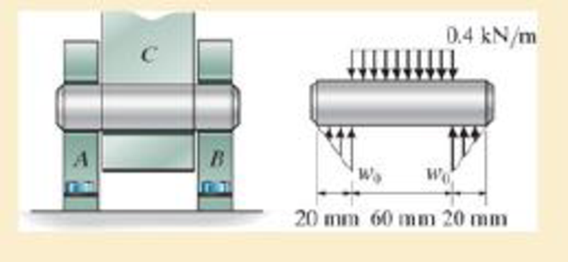
Prob. 6–32
Expert Solution & Answer
Want to see the full answer?
Check out a sample textbook solution
Students have asked these similar questions
*6-12. A reinforced concrete pier is used to support the
stringers for a bridge deck. Draw the shear and moment
diagrams for the pier when it is subjected to the stringer
loads shown. Assume the columns at A and B exert only
vertical reactions on the pier.
60 kN
60 kN
35 kN 35 kN 35 kN
m1m1.5 m 1.5 m 1 m 1m
60 KN 35 KN 35 KN 35 K 6o
ITT
im im
12-5 kN
V(KN)
525
MCKNm)
334
6-70. The strut on the utility pole supports the cable having a weight of 600 lb. Determine the
absolute maximum bending stress in the strut if A, B, and C are assumed to be pinned.
Problem 6-70
1.5 ft
C
A
-2 ft
- 4 ft
B
2 in.
I
600 lb
4 in.
Determine the internal normal force, shear force, and moment at points D and E in the
compound beam. Point E is located just to the left of the 10kN concentrated load. Assume the
support at A is fixed and the connection at B is a pin.
2 kN/m
D
E
-1.5 m 1.5 m 1.5 m----1.5m-
---
10 KN
--
Chapter 6 Solutions
MECHANICS OF MATERIALS-TEXT
Ch. 6.2 - In each case, the beam is subjected to the...Ch. 6.2 - and then draw the shear and moment diagrams for...Ch. 6.2 - In each case, express the shear and moment...Ch. 6.2 - In each case, express the shear and moment...Ch. 6.2 - In each case, express the shear and moment...Ch. 6.2 - In each case, draw the shear and moment diagrams...Ch. 6.2 - In each case, draw the shear and moment diagrams...Ch. 6.2 - In each case, draw the shear and moment diagrams...Ch. 6.2 - In each case, draw the shear and moment diagrams...Ch. 6.2 - If the force applied to the handle of the load...
Ch. 6.2 - Draw the shear and moment diagrams for the shaft....Ch. 6.2 - The crane is used to support the engine, which has...Ch. 6.2 - Prob. 6.4PCh. 6.2 - •6–5. Draw the shear and moment diagrams for the...Ch. 6.2 - Express the internal shear and moment in terms of...Ch. 6.2 - Prob. 6.7PCh. 6.2 - Prob. 6.8PCh. 6.2 - Prob. 6.9PCh. 6.2 - Members ABC and BD of the counter chair are...Ch. 6.2 - Prob. 6.11PCh. 6.2 - A reinforced concrete pier is used to support the...Ch. 6.2 - Prob. 6.13PCh. 6.2 - The industrial robot is held in the stationary...Ch. 6.2 - Determine the placement distance a of the roller...Ch. 6.2 - Express the internal shear and moment in the...Ch. 6.2 - Draw the shear and moment diagrams for the beam,...Ch. 6.2 - Draw the shear and moment diagrams for the beam....Ch. 6.2 - Draw the shear and moment diagrams for the...Ch. 6.2 - The 150-lb man sits in the center of the boat,...Ch. 6.2 - Prob. 6.22PCh. 6.2 - The footing supports the load transmitted by the...Ch. 6.2 - Express the shear and moment in terms of x for 0 ...Ch. 6.2 - Draw the shear and moment diagrams for the beam...Ch. 6.2 - Draw the shear and moment diagrams for the beam....Ch. 6.2 - Draw the shear and moment diagrams for the beam....Ch. 6.2 - Prob. 6.29PCh. 6.2 - 6–30. The beam is bolted or pinned at A and rests...Ch. 6.2 - The support at A allows the beam to slide freely...Ch. 6.2 - The smooth pin is supported by two leaves A and B...Ch. 6.2 - The shaft is supported by a smooth thrust bearing...Ch. 6.2 - Draw the shear and moment diagrams for the...Ch. 6.2 - Draw the shear and moment diagrams for the beam....Ch. 6.2 - Prob. 6.36PCh. 6.2 - Draw the shear and moment diagrams for the beam...Ch. 6.2 - The beam is used to support a uniform load along...Ch. 6.2 - Draw the shear and moment diagrams for the double...Ch. 6.2 - Draw the shear and moment diagrams for the simply...Ch. 6.2 - The compound beam is fixed at A, pin connected at...Ch. 6.2 - Draw the shear and moment diagrams for the...Ch. 6.2 - The compound beam is fixed at A, pin connected at...Ch. 6.2 - Draw the shear and moment diagrams for the beam....Ch. 6.2 - A short link at B is used to connect beams AB and...Ch. 6.2 - 6–46. Determine the placement b of the hooks to...Ch. 6.4 - Determine the moment of inertia of the cross...Ch. 6.4 - Determine the location of the centroid, y, and the...Ch. 6.4 - In each case, show how the bending stress acts on...Ch. 6.4 - Sketch the bending stress distribution over each...Ch. 6.4 - If the beam is subjected to a bending moment of M...Ch. 6.4 - If the beam is subjected to a bending moment of M...Ch. 6.4 - If the beam is subjected to a bending moment of M...Ch. 6.4 - If the beam is subjected to a bending moment of M...Ch. 6.4 - If the beam is subjected to a bending moment of M...Ch. 6.4 - Prob. 6.47PCh. 6.4 - Determine the moment M that will produce a maximum...Ch. 6.4 - Determine the maximum tensile and compressive...Ch. 6.4 - 6–50. A member has the triangular cross section...Ch. 6.4 - Prob. 6.51PCh. 6.4 - Prob. 6.52PCh. 6.4 - Prob. 6.53PCh. 6.4 - If the built-up beam is subjected to an internal...Ch. 6.4 - If the built-up beam is subjected to an internal...Ch. 6.4 - Prob. 6.56PCh. 6.4 - Prob. 6.57PCh. 6.4 - Prob. 6.58PCh. 6.4 - Prob. 6.59PCh. 6.4 - Prob. 6.60PCh. 6.4 - 6–61. The beam is subjected to a moment of 15 kip...Ch. 6.4 - 6–62. A box beam is constructed from four pieces...Ch. 6.4 - Prob. 6.63PCh. 6.4 - The axle of the freight car is subjected to a...Ch. 6.4 - A shaft is made of a polymer having an elliptical...Ch. 6.4 - Solve Prob. 6-65 if the moment M = 50 N m is...Ch. 6.4 - Prob. 6.67PCh. 6.4 - The shaft is supported by smooth journal bearings...Ch. 6.4 - Prob. 6.69PCh. 6.4 - Prob. 6.70PCh. 6.4 - The boat has a weight of 2300 lb and a center of...Ch. 6.4 - Determine the absolute maximum bending stress in...Ch. 6.4 - Determine the smallest allowable diameter of the...Ch. 6.4 - The pin is used to connect the three links...Ch. 6.4 - The shaft is supported by a thrust bearing at A...Ch. 6.4 - Prob. 6.76PCh. 6.4 - If the beam is subjected to an internal moment of...Ch. 6.4 - If the allowable tensile and compressive stress...Ch. 6.4 - If the beam is subjected to an internal moment of...Ch. 6.4 - If the beam is subjected to a moment of M = 100 kN...Ch. 6.4 - If the beam is made of material having an...Ch. 6.4 - The shaft is supported by a smooth thrust bearing...Ch. 6.4 - The shaft is supported by a thrust bearing at A...Ch. 6.4 - If the intensity of the load w = 15 kN/m,...Ch. 6.4 - If the allowable bending stress is allow = 150...Ch. 6.4 - Prob. 6.86PCh. 6.4 - Prob. 6.87PCh. 6.4 - *6–88. If the beam has a square cross section of 9...Ch. 6.4 - If the compound beam in Prob. 642 has a square...Ch. 6.4 - If the beam in Prob. 628 has a rectangular cross...Ch. 6.4 - Determine the absolute maximum bending stress in...Ch. 6.4 - Determine, to the nearest millimeter, the smallest...Ch. 6.4 - 6–93. The wing spar ABD of a light plane is made...Ch. 6.4 - Prob. 6.94PCh. 6.4 - Prob. 6.95PCh. 6.4 - A log that is 2 ft in diameter is to be cut into a...Ch. 6.4 - A log that is 2 ft in diameter is to be cut into a...Ch. 6.4 - If the beam in Prob.63 has a rectangular cross...Ch. 6.4 - Prob. 6.99PCh. 6.4 - If d = 450 mm, determine the absolute maximum...Ch. 6.4 - If the allowable bending stress is allow = 6 MPa,...Ch. 6.4 - Prob. 6.102PCh. 6.4 - 6–103. If the overhanging beam is made of wood...Ch. 6.5 - Determine the bending stress at corners A and B....Ch. 6.5 - Determine the maximum bending stress in the beams...Ch. 6.5 - The member has a square cross section and is...Ch. 6.5 - The member has a square cross section and is...Ch. 6.5 - Consider the general case of a prismatic beam...Ch. 6.5 - 6–107. If the beam is subjected to the internal...Ch. 6.5 - 6-108. If the wood used for the T-beam has an...Ch. 6.5 - 6-109. The box beam is subjected to the internal...Ch. 6.5 - 6-110. If the wood used for the box beam has an...Ch. 6.5 - 6-111. If the beam is subjected to the internal...Ch. 6.5 - 6-112. If the beam is made from a material having...Ch. 6.5 - Prob. 6.113PCh. 6.5 - 6-114. The T-beam is subjected to a bending moment...Ch. 6.5 - 6-115. The beam has a rectangular cross section....Ch. 6.5 - For the section, Iy' = 31.7(10-6) m4, Iz' =...Ch. 6.5 - For the section, Iy' = 31.7(10-6) m4, Iz' =...Ch. 6.5 - If the applied distributed loading of w = 4 kN/m...Ch. 6.5 - Determine the maximum allowable intensity w of the...Ch. 6.9 - The composite beam is made of steel (A) bonded to...Ch. 6.9 - The composite beam is made of steel (A) bonded to...Ch. 6.9 - Segment A of the composite beam is made from...Ch. 6.9 - Segment A of the composite beam is made from...Ch. 6.9 - Prob. 6.124PCh. 6.9 - The wooden section of the beam is reinforced with...Ch. 6.9 - The wooden section of the beam is reinforced with...Ch. 6.9 - Prob. 6.127PCh. 6.9 - The steel channel is used to reinforce the wood...Ch. 6.9 - Prob. 6.129PCh. 6.9 - 6-130. The beam is made from three types of...Ch. 6.9 - 6-131. The concrete beam is reinforced with three...Ch. 6.9 - *6-132. The wide-flange section is reinforced with...Ch. 6.9 - Prob. 6.133PCh. 6.9 - If the beam is subjected to a moment of M = 45 kN...Ch. 6.9 - Prob. 6.135PCh. 6.9 - For the curved beam in Fig. 640a, show that when...Ch. 6.9 - The curved member is subjected to the moment of M...Ch. 6.9 - The curved member is made from material having an...Ch. 6.9 - The curved beam is subjected to a moment of M = 40...Ch. 6.9 - The curved beam is made from material having an...Ch. 6.9 - If P = 3 kN, determine the bending stress at...Ch. 6.9 - If the maximum bending stress at section a-a is...Ch. 6.9 - The elbow of the pipe has an outer radius of 0.75...Ch. 6.9 - Prob. 6.144PCh. 6.9 - Prob. 6.145PCh. 6.9 - Prob. 6.146PCh. 6.9 - Prob. 6.147PCh. 6.9 - Prob. 6.148PCh. 6.9 - Prob. 6.149PCh. 6.9 - 6-150. The bar is subjected to a moment of M = 153...Ch. 6.9 - Prob. 6.151PCh. 6.9 - Prob. 6.152PCh. 6.9 - Prob. 6.153PCh. 6.9 - 6-154. The simply supported notched bar is...Ch. 6.9 - Prob. 6.155PCh. 6.9 - *6-156. Determine the length L of the center...Ch. 6.9 - Prob. 6.157PCh. 6.10 - Determine the shape factor for the wide-flange...Ch. 6.10 - 6-159. The beam is made of an elastic plastic...Ch. 6.10 - Prob. 6.160PCh. 6.10 - Prob. 6.161PCh. 6.10 - Prob. 6.162PCh. 6.10 - Determine the plastic moment Mp that can be...Ch. 6.10 - Determine the shape factor for the beam. Prob....Ch. 6.10 - The beam is made of elastic perfectly plastic...Ch. 6.10 - Determine the shape factor for the beam. Prob....Ch. 6.10 - The beam is made of an elastic perfectly plastic...Ch. 6.10 - Prob. 6.168PCh. 6.10 - Prob. 6.169PCh. 6.10 - 6-170. The box beam is made from an...Ch. 6.10 - 6-171. The beam is made from elastic-perfectly...Ch. 6.10 - *6-172. Determine the shape factor for the...Ch. 6.10 - Prob. 6.173PCh. 6.10 - Prob. 6.174PCh. 6.10 - 6-175. The box beam is made from an...Ch. 6.10 - The wide-flange member is made from an elastic...Ch. 6.10 - Prob. 6.177PCh. 6.10 - The plexiglass bar has a stress-strain curve that...Ch. 6.10 - The stress-strain diagram for a titanium alloy can...Ch. 6.10 - A beam is made from polypropylene plastic and has...Ch. 6.10 - Prob. 6.181PCh. 6.10 - The bar is made of an aluminum alloy having a...Ch. 6 - Using appropriate measurements and data, explain...Ch. 6 - Determine the shape factor for the wide-flange...Ch. 6 - Prob. 6.184RPCh. 6 - The compound beam consists of two segments that...Ch. 6 - The composite beam consists of a wood core and two...Ch. 6 - 6-187. Solve Prob. 6-186 if the moment is applied...Ch. 6 - If it resists a moment of M = 125 N m, determine...Ch. 6 - Determine the maximum bending stress in the handle...Ch. 6 - The curved beam is subjected to a bending moment...Ch. 6 - Determine the shear and moment in the beam as...Ch. 6 - A wooden beam has a square cross section as shown...Ch. 6 - Draw the shear and moment diagrams for the shaft...Ch. 6 - The strut has a square cross section a by a and is...
Knowledge Booster


Learn more about
Need a deep-dive on the concept behind this application? Look no further. Learn more about this topic, mechanical-engineering and related others by exploring similar questions and additional content below.Similar questions
- 20 mm 20 mm 4. The simply supported beam on the right is built up from three boards by nailing them together as shown. If P = 12 kN, determine the maximum allowable spacing s of the nails to support the load, if each nail can resist a shear force of 1.5 kN. 1 m m B 100 mm 25 mm- 25 mm 200 mm 25 mmarrow_forward6-73. Determine the absolute maximum live moment in the girder bridge due to the loading shown. The load is applied directly to the girder. 2400 Ib 1800 lb 10 ft- A C B D 15 ft -- 15 ft – 15 ft - Prob. 6–73arrow_forwardDetermine the normal force, shear force and moment at sections passing through points E and F Member BC is pinned at B and there is a smooth slot in it at C. The pin at C is fixed to member CDarrow_forward
- Determine the internal normal force at point C, if F = 48 kN . Determine the shear force at point C Determine the bending moment at point Carrow_forward1-7. The cable will fail when subjected to a tension of 800ON Determine the largest vertical load P the frame will support and calculate the internal normal force, shear force, and moment at the cross section through point C for this loading. B 0.1' m 0.5 m A -0.75 m- -0.75 m -0.75 m Parrow_forwardDetermine the internal normal force, shear force, and bending moment at points D and E of the bell crank that is pinned at A and supported by a short link BC.arrow_forward
- DRAW THE DIAGRAM OF EVERY ANALYZED PART AND LABEL THE VALUE OF SHEAR AND MOMENT. B 3m 10 kN C 3m D 2m THET A hinge at D 6m E 20 kN/m 4marrow_forwardThe tapered beam supports the concentrated force P at its center. Determine the absolute maximum bending stress in the beam. The reactions at the supports are vertical.arrow_forwardDetermine the internal normal force, shear force, and bending moment at point C in the beam. 10 kN 60 kN-m A- B- - 2 m- m--1 m- -2 m-arrow_forward
- Draw the Shear Force and Bending Moment Diagram of the following Structures 155 kN 37 kN/m Hinge A -5 m- B -2.5 m2.5 m-arrow_forwardThe pin is used to connect the three links together. Due to wear, the load is distributed over the top and bottom of the pin as shown on the free-body diagram. If the diameter of the pin is 0.40 in., determine the maximum bending stress on the cross-sectional area at the center section a–a. For the solution it is first necessary to determine the load intensities w1 and w2.arrow_forwardDetermine the internal normal force, shear force, and bending moment at point E. 2 kN/m - 6 kN m B E -3 m +1.5 m+1.5 m- 5 kNarrow_forward
arrow_back_ios
SEE MORE QUESTIONS
arrow_forward_ios
Recommended textbooks for you
 Elements Of ElectromagneticsMechanical EngineeringISBN:9780190698614Author:Sadiku, Matthew N. O.Publisher:Oxford University Press
 Mechanics of Materials (10th Edition)Mechanical EngineeringISBN:9780134319650Author:Russell C. HibbelerPublisher:PEARSON
 Thermodynamics: An Engineering ApproachMechanical EngineeringISBN:9781259822674Author:Yunus A. Cengel Dr., Michael A. BolesPublisher:McGraw-Hill Education
 Control Systems EngineeringMechanical EngineeringISBN:9781118170519Author:Norman S. NisePublisher:WILEY
 Mechanics of Materials (MindTap Course List)Mechanical EngineeringISBN:9781337093347Author:Barry J. Goodno, James M. GerePublisher:Cengage Learning
 Engineering Mechanics: StaticsMechanical EngineeringISBN:9781118807330Author:James L. Meriam, L. G. Kraige, J. N. BoltonPublisher:WILEY
Elements Of Electromagnetics
Mechanical Engineering
ISBN:9780190698614
Author:Sadiku, Matthew N. O.
Publisher:Oxford University Press
Mechanics of Materials (10th Edition)
Mechanical Engineering
ISBN:9780134319650
Author:Russell C. Hibbeler
Publisher:PEARSON
Thermodynamics: An Engineering Approach
Mechanical Engineering
ISBN:9781259822674
Author:Yunus A. Cengel Dr., Michael A. Boles
Publisher:McGraw-Hill Education
Control Systems Engineering
Mechanical Engineering
ISBN:9781118170519
Author:Norman S. Nise
Publisher:WILEY
Mechanics of Materials (MindTap Course List)
Mechanical Engineering
ISBN:9781337093347
Author:Barry J. Goodno, James M. Gere
Publisher:Cengage Learning
Engineering Mechanics: Statics
Mechanical Engineering
ISBN:9781118807330
Author:James L. Meriam, L. G. Kraige, J. N. Bolton
Publisher:WILEY
Understanding Shear Force and Bending Moment Diagrams; Author: The Efficient Engineer;https://www.youtube.com/watch?v=C-FEVzI8oe8;License: Standard YouTube License, CC-BY
Bending Stress; Author: moodlemech;https://www.youtube.com/watch?v=9QIqewkE6xM;License: Standard Youtube License