
Concept explainers
Videos
A floor truss is loaded as shown. Determine the force members CF, EF, and EG.
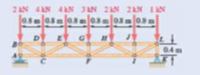
Fig. P6.47 and P6.48
The force in the members
Answer to Problem 6.47P
The force in the members
Explanation of Solution
The floor truss is loaded as shown in the figure. The free body diagram of the given arrangement is given by Figure 1.
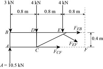
Figure 1
For the entire truss, the force along the positive
The moment of force in the counter clockwise direction about
Solve for
This implies that
The force in the positive
Substitute
This implies
For the section
The force in the positive
For the section
Conclusion:
Substitute
Substitute
Substitute
Therefore, the force in the members
Want to see more full solutions like this?
Chapter 6 Solutions
VECTOR MECHANICS FOR ENGINEERS: STATICS


- *Set P = 7 kN* Pt A: Determine the forces in members DC, CB, and BA of the truss. State whether the members are in tension or compression. Pt B: Determine the forces in members DE and EA of the truss. State whether the members are in tension or compression. Pt C: Determine the forces in members CE and BE of the truss. State whether the members are in tension or compression.arrow_forwardThe cab and motor units of the front-end loader shown are connected by a vertical pin located 2 m behind the cab wheels. The distance from C to D is 1 m. The center of gravity of the 300-kN motor unit is located at Gm, while the centers of gravity of the 100-kN cab and 75-kN load are located, respectively, at Gc and Gl. Knowing that the front-end loader is at rest with its brakes released, determine(a) the reactions at each of the four wheels, (b) the forces exertedon the motor unit at C and D.arrow_forwardArm ABC is connected by pins to a collar at B and to crank CD at C Neglecting the effect of friction, determine the couple M required to hold the system in equilibrium 'when 0= 0.Fig.P6.133arrow_forward
- The cab and motor units of the front-end loader shown are connected by a vertical pin located 2 m behind the cab wheels. The distance from C to D is 1 m. The center of gravity of the 300-kN motor unit is located at Gm , while the centers of gravity of the 100-kN cab and 75-kN load are located, respectively, at Gc and GI. . Knowing that the machine is at rest with its brakes released, determine (a) the reactions at each of the four wheels, (b) the forces exerted on the motor unit at C and D.arrow_forwardDetermine the force in members BD and DE of the truss shown.arrow_forwardSolve Prob. 6.24 assuming that the cables hanging from the right side of the tower have fallen to the ground.(Reference to Problem 6.24):The portion of truss shown represents the upper part of a power transmission line tower. For the given loading, determine the force in each of the members located above HJ . State whether each member is in tension or compression.arrow_forward
- The structure shown is composed of an AGJ truss and a KLMO truss connected by the AL link. If it is known that P = 2 kN; R = 5kN; a = 1.5 m and b = 2m, determine:to. The value of the force Q, necessary to keep the system in equilibrium.b. The axial loads of the reinforcement elements. (need free body diagrams)arrow_forwardA 40-lb roller of 8-in. diameter, which is to be used on a tile floor,is resting directly on the subflooring as shown. Knowing that the thickness of each tile is 0.3 in., determine the force P required to move the roller onto the tiles if the roller is (a) pushed to the left,(b) pulled to the right.arrow_forwardUsing the method of joints, determine the force in each member of the trusses shown. State whether each member is in tension (T) or compression (C).arrow_forward
- The T-shaped bracket shown is supported by a small wheel at E and pegs at C and D . Neglecting the effect of friction, determine (a) the smallest value of 0 for which the equilibrium of the bracket is maintained, (b) the corresponding reactions at C, D, and E.arrow_forwardThe position of boom ABC is controlled by the hydraulic cylinder BD . For the loading shown, determine the force exerted by the hydraulic cylinder on pin B when θ = 70°.arrow_forwardMembers ABC and CDE are pin-connected at C and supported by four links. For the loading shown, determine the force in each link.arrow_forward
 Elements Of ElectromagneticsMechanical EngineeringISBN:9780190698614Author:Sadiku, Matthew N. O.Publisher:Oxford University Press
 Mechanics of Materials (10th Edition)Mechanical EngineeringISBN:9780134319650Author:Russell C. HibbelerPublisher:PEARSON
 Thermodynamics: An Engineering ApproachMechanical EngineeringISBN:9781259822674Author:Yunus A. Cengel Dr., Michael A. BolesPublisher:McGraw-Hill Education
 Control Systems EngineeringMechanical EngineeringISBN:9781118170519Author:Norman S. NisePublisher:WILEY
 Mechanics of Materials (MindTap Course List)Mechanical EngineeringISBN:9781337093347Author:Barry J. Goodno, James M. GerePublisher:Cengage Learning
 Engineering Mechanics: StaticsMechanical EngineeringISBN:9781118807330Author:James L. Meriam, L. G. Kraige, J. N. BoltonPublisher:WILEY