
Engineering Mechanics: Statics
13th Edition
ISBN: 9780132915540
Author: Russell C. Hibbeler
Publisher: Prentice Hall
expand_more
expand_more
format_list_bulleted
Videos
Textbook Question
Chapter 6.3, Problem 2FP
State if the members are in tension or compression.
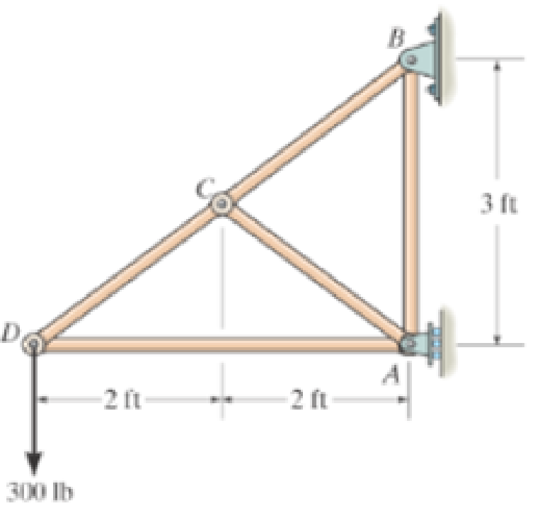
Prob. F6-2
Expert Solution & Answer

Learn your wayIncludes step-by-step video

schedule08:02
Students have asked these similar questions
Determine the force in each member of the loaded truss. The forces are positive if in tension, negative if in compression.Assume F = 2910 N, a = 1.8 m, b = 3.6 m, θ= 40°.
Find the force in member AB of the truss and indicate whether it is in Tension or Compression, given:
F = 35 lbs, θ = 46 °
Determine the forces in members BJ, BI, CI, CH, DG, DH, and EG of the loaded truss. All triangles are 45°-45°-90°. The forces are positive if in tension, negative if in compression.
Chapter 6 Solutions
Engineering Mechanics: Statics
Ch. 6.3 - State if the members are in tension or...Ch. 6.3 - State if the members are in tension or...Ch. 6.3 - Prob. 3FPCh. 6.3 - Determine the greatest load P that can be applied...Ch. 6.3 - Identify the zero-force members in the truss....Ch. 6.3 - State if the members are in tension or...Ch. 6.3 - Prob. 1PCh. 6.3 - Prob. 2PCh. 6.3 - Determine the force in each member of the truss,...Ch. 6.3 - Determine the force in each member of the truss,...
Ch. 6.3 - Prob. 5PCh. 6.3 - Determine the force in each member of the truss...Ch. 6.3 - Determine the force in each member of the Pratt...Ch. 6.3 - Prob. 8PCh. 6.3 - Prob. 9PCh. 6.3 - Prob. 10PCh. 6.3 - Determine the force in each member of the truss...Ch. 6.3 - Prob. 12PCh. 6.3 - Prob. 13PCh. 6.3 - Prob. 14PCh. 6.3 - Prob. 15PCh. 6.3 - State whether the members are in tension or...Ch. 6.3 - If the maximum force that any member can support...Ch. 6.3 - Prob. 18PCh. 6.3 - Prob. 19PCh. 6.3 - Prob. 20PCh. 6.3 - Prob. 21PCh. 6.3 - Determine the force in each member of the double...Ch. 6.3 - Prob. 23PCh. 6.3 - Prob. 24PCh. 6.3 - Prob. 25PCh. 6.3 - Prob. 26PCh. 6.4 - Determine the force in members BC, CF, and FE....Ch. 6.4 - State if the members are in tension or...Ch. 6.4 - State if the members are in tension or...Ch. 6.4 - State if the members are in tension or...Ch. 6.4 - State if the members are in tension or...Ch. 6.4 - State if the members are in tension or...Ch. 6.4 - Determine the force in members HG, HE and DE of...Ch. 6.4 - Prob. 28PCh. 6.4 - Prob. 29PCh. 6.4 - Prob. 30PCh. 6.4 - State if these members are in tension or...Ch. 6.4 - State if these members are in tension or...Ch. 6.4 - Prob. 33PCh. 6.4 - Prob. 34PCh. 6.4 - State if these members are in tension or...Ch. 6.4 - Determine the force in members CD, CF, and CG and...Ch. 6.4 - Determine the force in members GF, FB, and BC of...Ch. 6.4 - Prob. 38PCh. 6.4 - Prob. 39PCh. 6.4 - Prob. 40PCh. 6.4 - Prob. 41PCh. 6.4 - Prob. 42PCh. 6.4 - Prob. 43PCh. 6.4 - Prob. 44PCh. 6.4 - Prob. 45PCh. 6.4 - Prob. 46PCh. 6.4 - Prob. 47PCh. 6.4 - Prob. 48PCh. 6.4 - Prob. 49PCh. 6.6 - Determine the force P needed to hold the 60-lb...Ch. 6.6 - Determine the horizontal and vertical components...Ch. 6.6 - If a 100-N force is applied to the handles of the...Ch. 6.6 - Prob. 16FPCh. 6.6 - Determine the normal force that the 100-lb plate A...Ch. 6.6 - Also, determine the proper placement x of the hook...Ch. 6.6 - Determine the components of reaction at A and B....Ch. 6.6 - Determine the reactions at D. Prob. F6-20Ch. 6.6 - Determine the components of reaction at A and C....Ch. 6.6 - Determine the components of reaction at C. Prob....Ch. 6.6 - Determine the components of reaction at E. Prob....Ch. 6.6 - Determine the components of reaction at D and the...Ch. 6.6 - The block weighs 100 lb. Prob. 6-62Ch. 6.6 - Prob. 62PCh. 6.6 - Prob. 63PCh. 6.6 - Prob. 64PCh. 6.6 - Prob. 65PCh. 6.6 - Prob. 66PCh. 6.6 - Prob. 67PCh. 6.6 - Prob. 68PCh. 6.6 - Also, what are the horizontal and vertical...Ch. 6.6 - Prob. 70PCh. 6.6 - Prob. 71PCh. 6.6 - Prob. 72PCh. 6.6 - Prob. 73PCh. 6.6 - Determine the horizontal and vertical components...Ch. 6.6 - Determine the horizontal and vertical components...Ch. 6.6 - Prob. 76PCh. 6.6 - Prob. 77PCh. 6.6 - Prob. 78PCh. 6.6 - The toggle clamp is subjected to a force F at the...Ch. 6.6 - Determine the force P exerted on each of the...Ch. 6.6 - Prob. 81PCh. 6.6 - Determine the force in the guy cable AI and the...Ch. 6.6 - Prob. 83PCh. 6.6 - Prob. 84PCh. 6.6 - Prob. 85PCh. 6.6 - If the wheel at A exerts a normal force of FA = 80...Ch. 6.6 - Prob. 87PCh. 6.6 - Prob. 88PCh. 6.6 - Prob. 89PCh. 6.6 - Determine the force that the jaws J of the metal...Ch. 6.6 - When the walking beam ABC is horizontal, the force...Ch. 6.6 - Prob. 92PCh. 6.6 - Prob. 93PCh. 6.6 - Determine the total force he must exert on bar AB...Ch. 6.6 - Determine the total force he must exert on bar AB...Ch. 6.6 - Prob. 96PCh. 6.6 - Prob. 97PCh. 6.6 - Determine the horizontal and vertical components...Ch. 6.6 - If a clamping force of 300 N is required at A,...Ch. 6.6 - If a force of F = 350 N is applied to the handle...Ch. 6.6 - Prob. 101PCh. 6.6 - Prob. 102PCh. 6.6 - Prob. 103PCh. 6.6 - Prob. 104PCh. 6.6 - Prob. 105PCh. 6.6 - If d = 0.75 ft and the spring has an unstretched...Ch. 6.6 - If a force of F = 50 lb is applied to the pads at...Ch. 6.6 - Determine the force in the hydraulic cylinder AB...Ch. 6.6 - Prob. 109PCh. 6.6 - Prob. 110PCh. 6.6 - Prob. 111PCh. 6.6 - If the sprig has a stiffness of k = 15 lb/in., and...Ch. 6.6 - Prob. 113PCh. 6.6 - Prob. 114PCh. 6.6 - If only vertical forces are supported at the...Ch. 6.6 - Determine the resultant forces at pins B and C on...Ch. 6.6 - Determine the force in each member of the truss...Ch. 6.6 - Determine the horizontal and vertical components...Ch. 6.6 - Prob. 123RPCh. 6.6 - Prob. 124RPCh. 6.6 - Prob. 125RPCh. 6.6 - Determine the force in each member of the truss...
Additional Engineering Textbook Solutions
Find more solutions based on key concepts
3.43 Determine the magnitude, direction, and sense of the resultant of the forces shown. Determine where the re...
Applied Statics and Strength of Materials (6th Edition)
The pipe has a mass of 12 kg/m. If it is fixed to the wall at A, determine the resultant internal loadings acti...
Mechanics of Materials (10th Edition)
The composite beam is made of steel (A) bonded to brass (B) and has the cross section shown. If it is subjected...
Mechanics of Materials
Determine the resultant internal loadings acting on the cross sections at points F and G of the frame. Probs. 7...
Statics and Mechanics of Materials (5th Edition)
ICA 2-1
For each of the following situations, indicate whether you think the action is ethical or unethical or ...
Thinking Like an Engineer: An Active Learning Approach (4th Edition)
Figure 8.12shows a portion of a fire protection system in which a pump draws water at 60 F from a reservoir and...
Applied Fluid Mechanics (7th Edition)
Knowledge Booster


Learn more about
Need a deep-dive on the concept behind this application? Look no further. Learn more about this topic, mechanical-engineering and related others by exploring similar questions and additional content below.Similar questions
- Determine the force in each member of the truss and state if the members are in tension or compression. Set P1 = 9 kN, P2 = 15 kN. using the principle of static equilibrium of momentsarrow_forwardDetermine the force in each member of the truss and state if the members are in tension or compression. Set P1 = 3 kN, P2 = 6 kN. Show the updated FBD.arrow_forwardUsing Method Of Sections, Determine The Forces In Members CD And DF. 5 KN 4 KN 3 KN 2 KN |-3 M +-3m-+-3 M+-3m- 3.arrow_forward
- Determine the froce in each member of the truss. Assume the diagonals cannot support a compressive forcearrow_forwardDetermine the tension developed in cables OD and OB and the strut OC, required to support the 50-kg crate. The spring OA has an unstretched length of 0.8 m and stiffness kOA = 1.2 kN/m The force in the strut acts along the axis of the strut.arrow_forwardDetermine the forces on the DF, EF and EG members, indicating whether they are traction or compression. Use the section method.H = 83arrow_forward
- If the gap between C and the rigid wall at D is initially 0.15 mm, determine the support reactions at A and D when the force P = 200 kN is applied. The assembly is made of solid A-36 steel cylinders.arrow_forwardUsing the attached image, determine the force in each member of the truss and state if the members are in tension or compression. Set P1= 2 kN and P2= 1.5 kN. Use method of joint.arrow_forwardThe mobile crane is symmetrically supported by two outriggers at A and B to relieve the suspension of the vehicle on which it sits and to provide extra stability. Determine the vertical reactions at each of the two outriggers as a function of boom angle when the boom is carrying a 1.2 Mg load and the crane and truck have a combined mass of 18 Mg and the boom has a mass of 2 Mg. 0 = 45°arrow_forward
- Determine the force in the members' AB, AE, AF, BC, BE, CD, CE, DE, EF, and state if each member is in tension or compression. P1=9kN and P2=14kNarrow_forwardDetermine the force in member 2 of the assembly as shown if the support at joint 1 settles downward 25 mm. Take AE = 8(103) kN.arrow_forwardThe three A-36 steel wires each have a diameter of 2 mm and unloaded lengths of LAC = 1.60 m and LAB = LAD = 2.00 m. Determine the force in each wire after the 150-kg mass is suspended from the ring at A.arrow_forward
arrow_back_ios
SEE MORE QUESTIONS
arrow_forward_ios
Recommended textbooks for you
 Elements Of ElectromagneticsMechanical EngineeringISBN:9780190698614Author:Sadiku, Matthew N. O.Publisher:Oxford University Press
 Mechanics of Materials (10th Edition)Mechanical EngineeringISBN:9780134319650Author:Russell C. HibbelerPublisher:PEARSON
 Thermodynamics: An Engineering ApproachMechanical EngineeringISBN:9781259822674Author:Yunus A. Cengel Dr., Michael A. BolesPublisher:McGraw-Hill Education
 Control Systems EngineeringMechanical EngineeringISBN:9781118170519Author:Norman S. NisePublisher:WILEY
 Mechanics of Materials (MindTap Course List)Mechanical EngineeringISBN:9781337093347Author:Barry J. Goodno, James M. GerePublisher:Cengage Learning
 Engineering Mechanics: StaticsMechanical EngineeringISBN:9781118807330Author:James L. Meriam, L. G. Kraige, J. N. BoltonPublisher:WILEY
Elements Of Electromagnetics
Mechanical Engineering
ISBN:9780190698614
Author:Sadiku, Matthew N. O.
Publisher:Oxford University Press
Mechanics of Materials (10th Edition)
Mechanical Engineering
ISBN:9780134319650
Author:Russell C. Hibbeler
Publisher:PEARSON
Thermodynamics: An Engineering Approach
Mechanical Engineering
ISBN:9781259822674
Author:Yunus A. Cengel Dr., Michael A. Boles
Publisher:McGraw-Hill Education
Control Systems Engineering
Mechanical Engineering
ISBN:9781118170519
Author:Norman S. Nise
Publisher:WILEY
Mechanics of Materials (MindTap Course List)
Mechanical Engineering
ISBN:9781337093347
Author:Barry J. Goodno, James M. Gere
Publisher:Cengage Learning
Engineering Mechanics: Statics
Mechanical Engineering
ISBN:9781118807330
Author:James L. Meriam, L. G. Kraige, J. N. Bolton
Publisher:WILEY
Physics 33 - Fluid Statics (1 of 10) Pressure in a Fluid; Author: Michel van Biezen;https://www.youtube.com/watch?v=mzjlAla3H1Q;License: Standard YouTube License, CC-BY