
Engineering Mechanics: Statics & Dynamics (14th Edition)
14th Edition
ISBN: 9780133915426
Author: Russell C. Hibbeler
Publisher: PEARSON
expand_more
expand_more
format_list_bulleted
Videos
Textbook Question
Chapter 6.3, Problem 2PP
Identify the zero-force members in each truss.
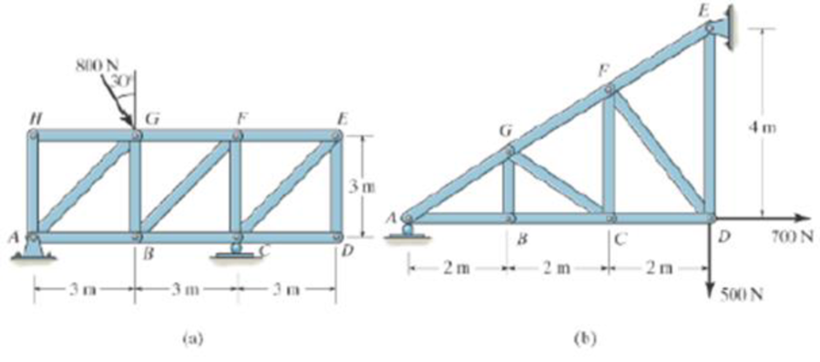
Prob. P6-2
Expert Solution & Answer
Want to see the full answer?
Check out a sample textbook solution
Students have asked these similar questions
Using Method Of Sections, Determine The Forces In Members CD And DF. 5 KN 4 KN 3 KN 2 KN |-3 M +-3m-+-3 M+-3m- 3.
Determine the froce in each member of the truss. Assume the diagonals cannot support a compressive force
Draw the free-body diagram of the uniform bar, which has a mass of 100 kg and a center of mass at G. The supports A, B, and C are smooth.
Chapter 6 Solutions
Engineering Mechanics: Statics & Dynamics (14th Edition)
Ch. 6.3 - In each case, calculate the support reactions and...Ch. 6.3 - Identify the zero-force members in each truss....Ch. 6.3 - Determine the force in each member of the truss....Ch. 6.3 - Determine the force in each member of the truss....Ch. 6.3 - Determine the force in each member of the truss....Ch. 6.3 - Determine the greatest load P that can be applied...Ch. 6.3 - Identify the zero-force members in the truss....Ch. 6.3 - Determine the force in each member of the truss....Ch. 6.3 - Determine the force in each member of the truss...Ch. 6.3 - Determine the force in each member of the truss...
Ch. 6.3 - Determine the force in each member of the truss....Ch. 6.3 - Determine the force in each member of the truss...Ch. 6.3 - Prob. 5PCh. 6.3 - Determine the force in each member of the truss,...Ch. 6.3 - Determine the force in each member of the truss...Ch. 6.3 - Determine the force in each member of the truss...Ch. 6.3 - Prob. 9PCh. 6.3 - Determine the force in each member of the truss...Ch. 6.3 - Determine the force in each member of the Pratt...Ch. 6.3 - Determine the force in each member of the truss...Ch. 6.3 - Determine the force in each member of the truss in...Ch. 6.3 - Members AB and BC can each support a maximum...Ch. 6.3 - Members AB and BC can each support a maximum...Ch. 6.3 - Determine the force in each member of the truss....Ch. 6.3 - If the maximum force that any member can support...Ch. 6.3 - Determine the force in each member of the truss...Ch. 6.3 - Determine the force in each member of the truss...Ch. 6.3 - Prob. 20PCh. 6.3 - Determine the force in each member of the truss...Ch. 6.3 - Determine the force in each member of the double...Ch. 6.3 - Prob. 23PCh. 6.3 - The maximum allowable tensile force in the members...Ch. 6.3 - Determine the force in each member of the truss in...Ch. 6.3 - The maximum allowable tensile force in the members...Ch. 6.4 - Determine the force in members BC, CF, and FE....Ch. 6.4 - Determine the force in members LK, KC, and CD of...Ch. 6.4 - Determine the force in members KJ, KD, and CD of...Ch. 6.4 - Determine the force in members EF, CF, and BC of...Ch. 6.4 - Determine the force in members GF, GD, and CD of...Ch. 6.4 - Determine the force in members DC, HI, and JI of...Ch. 6.4 - Determine the force in members DC, HC, and HI of...Ch. 6.4 - Determine the force in members ED, EH, and GH of...Ch. 6.4 - Determine the force in members HG, HE and DE of...Ch. 6.4 - Determine the force in members CD, HI, and CH of...Ch. 6.4 - Prob. 31PCh. 6.4 - Prob. 32PCh. 6.4 - Prob. 33PCh. 6.4 - Prob. 34PCh. 6.4 - Determine the force in members EF, CF, and BC, and...Ch. 6.4 - Determine the force in members AF, BF, and BC, and...Ch. 6.4 - Prob. 39PCh. 6.4 - Determine the force in members CD, CF, and CG and...Ch. 6.4 - Determine the force developed in members FE, EB,...Ch. 6.4 - Determine the force in members BC, HC, and HG....Ch. 6.4 - Determine the force in members CD, CJ, GJ, and CG...Ch. 6.4 - Determine the force in members BE, EF, and CB, and...Ch. 6.4 - Prob. 45PCh. 6.4 - Determine the force in members BC, CH, GH, and CG...Ch. 6.4 - Determine the force in members CD, CJ, and KJ and...Ch. 6.4 - Prob. 48PCh. 6.4 - Determine the force in members HI, FI, and EF of...Ch. 6.6 - In each case, identify any two-force members, and...Ch. 6.6 - Determine the force P needed to hold the 60-lb...Ch. 6.6 - Determine the horizontal and vertical components...Ch. 6.6 - If a 100-N force is applied to the handles of the...Ch. 6.6 - Determine the horizontal and vertical components...Ch. 6.6 - Determine the normal force that the 100-lb plate A...Ch. 6.6 - Determine the force P needed to lift the load....Ch. 6.6 - Prob. 19FPCh. 6.6 - Prob. 20FPCh. 6.6 - Determine the components of reaction at A and C....Ch. 6.6 - Determine the components of reaction at C. Prob....Ch. 6.6 - Determine the components of reaction at E. Prob....Ch. 6.6 - Determine the components of reaction at D and the...Ch. 6.6 - Determine the force P required to hold the 100-lb...Ch. 6.6 - In each case, determine the force P required to...Ch. 6.6 - Determine the force P required to hold the 50-kg...Ch. 6.6 - Determine the force P required to hold the 150-kg...Ch. 6.6 - Determine the horizontal and vertical components...Ch. 6.6 - Determine the horizontal and vertical components...Ch. 6.6 - Determine the force that the smooth rotor C exerts...Ch. 6.6 - The bridge frame consists of three segments which...Ch. 6.6 - Determine the reactions at supports A and B. Prob....Ch. 6.6 - Determine the horizontal and vertical components...Ch. 6.6 - Determine the reactions at the supports A, C, and...Ch. 6.6 - Determine the resultant force at pins A, B, and C...Ch. 6.6 - Determine the reactions at the supports at A, E,...Ch. 6.6 - The wall crane supports a load of 700 lb....Ch. 6.6 - The wall crane supports a load of 700 lb....Ch. 6.6 - Determine the horizontal and vertical components...Ch. 6.6 - The two-member structure is connected at C by a...Ch. 6.6 - The compound beam is pin supported at B and...Ch. 6.6 - When a force of 2 lb is applied to the handles of...Ch. 6.6 - The toggle clamp is subjected to a force F at the...Ch. 6.6 - The hoist supports the 125-kg engine. Determine...Ch. 6.6 - A 5-lb force is applied to the handles of the vise...Ch. 6.6 - Determine the force in members FD and DB of the...Ch. 6.6 - Determine the force that the smooth 20-kg cylinder...Ch. 6.6 - Prob. 85PCh. 6.6 - The pumping unit is used to recover oil. When the...Ch. 6.6 - Determine the force that the jaws J of the metal...Ch. 6.6 - Prob. 88PCh. 6.6 - Determine the horizontal and vertical components...Ch. 6.6 - The pipe cutter is clamped around the pipe P. If...Ch. 6.6 - Determine the force created in tire hydraulic...Ch. 6.6 - Determine the horizontal and vertical components...Ch. 6.6 - The constant moment of 50 N m is applied to the...Ch. 6.6 - Five coins are stacked in the smooth plastic...Ch. 6.6 - The nail cutter consists of the handle and the two...Ch. 6.6 - A man having a weight of 175 lb attempts to hold...Ch. 6.6 - Prob. 97PCh. 6.6 - The two member frame is pin connected at E. The...Ch. 6.6 - If the 300 kg drum has a center of mass at point...Ch. 6.6 - Operation of exhaust and intake valves in an...Ch. 6.6 - If a clamping force of 300 N is required at A,...Ch. 6.6 - If a force of F = 350 N is applied to the handle...Ch. 6.6 - Determine the horizontal and vertical components...Ch. 6.6 - The hydraulic crane is used to lift the 1400-lb...Ch. 6.6 - Determine force P on the cable if the spring is...Ch. 6.6 - Prob. 106PCh. 6.6 - If a force of F = 50 lb is applied to the pads at...Ch. 6.6 - The skid-steer loader has a mass of 1.18 Mg, and...Ch. 6.6 - Determine the force P on the cable if the spring...Ch. 6.6 - The spring has an unstretched length of 0.3 m....Ch. 6.6 - The spring has an unstretched length of 0.3 m....Ch. 6.6 - The piston C moves vertically between the two...Ch. 6.6 - Prob. 113PCh. 6.6 - The platform scale consists of a combination of...Ch. 6.6 - The three pin-connected members shown in the top...Ch. 6.6 - Determine the force in each member of the truss...Ch. 6.6 - Determine the force in each member of the truss...Ch. 6.6 - Determine the force in member GJ and GC of the...Ch. 6.6 - Determine the force in members GF, FB, and BC of...Ch. 6.6 - Determine the horizontal and vertical components...Ch. 6.6 - Determine the horizontal and vertical components...Ch. 6.6 - Determine the resultant forces at pins B and C on...
Additional Engineering Textbook Solutions
Find more solutions based on key concepts
4.44 Compute reactions at each support for the beam shown. The beam weight is 50 lb/ft.
Applied Statics and Strength of Materials (6th Edition)
Determine the internal normal force between lettered points on the cable and rod. Draw all necessary free-body ...
Mechanics of Materials (10th Edition)
In each case, determine the internal normal force between lettered points on the bar. Draw all necessary free-b...
Mechanics of Materials
What parts are included in the vehicle chassis?
Automotive Technology: Principles, Diagnosis, and Service (5th Edition)
Determine the resultant internal loadings acting on the cross sections at points F and G of the frame. Probs. 7...
Statics and Mechanics of Materials (5th Edition)
A 4-in-ductile iron pipe carries 0.20ft3/s of glycerin (sg = 1.26 ) at 100F. Is the flow laminar or turbulent?
Applied Fluid Mechanics (7th Edition)
Knowledge Booster


Learn more about
Need a deep-dive on the concept behind this application? Look no further. Learn more about this topic, mechanical-engineering and related others by exploring similar questions and additional content below.Similar questions
- The mobile crane is symmetrically supported by two outriggers at A and B to relieve the suspension of the vehicle on which it sits and to provide extra stability. Determine the vertical reactions at each of the two outriggers as a function of boom angle when the boom is carrying a 1.2 Mg load and the crane and truck have a combined mass of 18 Mg and the boom has a mass of 2 Mg. 0 = 45°arrow_forwardDetermine the forces in members BJ, BI, CI, CH, DG, DH, and EG of the loaded truss. All triangles are 45°-45°-90°. The forces are positive if in tension, negative if in compression.arrow_forwardGiven the Howe truss, determine the force in members DF, DG, and EG.arrow_forward
- Determine the force in each member of the truss and state if the members are in tension or compression. Set P1 = 9 kN, P2 = 15 kN. using the principle of static equilibrium of momentsarrow_forwardDetermine the support reactions at the smooth journal bearings A, B, and C of the pipe assembly.arrow_forwardDetermine the forces on the DF, EF and EG members, indicating whether they are traction or compression. Use the section method.H = 83arrow_forward
- The ramp is used as passengers board a small commuter airplane. The total mass of the ramp and six passengers is 730 kg with a mass center at G. Determine the force in the hydraulic cylinder AB (positive if in tension, negative if in compression) and the magnitude of the pin reaction at C.arrow_forwardDetermine the force in each member of the truss and state if the members are in tension or compression. Set P1 = 3 kN, P2 = 6 kN. Show the updated FBD.arrow_forwardUsing the attached image, determine the force in each member of the truss and state if the members are in tension or compression. Set P1= 2 kN and P2= 1.5 kN. Use method of joint.arrow_forward
- Determine the force in each member of the loaded truss. The forces are positive if in tension, negative if in compression.Assume F = 2910 N, a = 1.8 m, b = 3.6 m, θ= 40°.arrow_forwardDraw the free body diagrams of (a) the whole structure, (b) members AB, BC and AC individually and (c) the pin at B. The forces in the free body diagrams must be named consistently.arrow_forwardDetermine the resultant force at pins A, B, and C on the three-member frame. Given: F = 40N, w = 10, L = 1.arrow_forward
arrow_back_ios
SEE MORE QUESTIONS
arrow_forward_ios
Recommended textbooks for you
 Elements Of ElectromagneticsMechanical EngineeringISBN:9780190698614Author:Sadiku, Matthew N. O.Publisher:Oxford University Press
 Mechanics of Materials (10th Edition)Mechanical EngineeringISBN:9780134319650Author:Russell C. HibbelerPublisher:PEARSON
 Thermodynamics: An Engineering ApproachMechanical EngineeringISBN:9781259822674Author:Yunus A. Cengel Dr., Michael A. BolesPublisher:McGraw-Hill Education
 Control Systems EngineeringMechanical EngineeringISBN:9781118170519Author:Norman S. NisePublisher:WILEY
 Mechanics of Materials (MindTap Course List)Mechanical EngineeringISBN:9781337093347Author:Barry J. Goodno, James M. GerePublisher:Cengage Learning
 Engineering Mechanics: StaticsMechanical EngineeringISBN:9781118807330Author:James L. Meriam, L. G. Kraige, J. N. BoltonPublisher:WILEY
Elements Of Electromagnetics
Mechanical Engineering
ISBN:9780190698614
Author:Sadiku, Matthew N. O.
Publisher:Oxford University Press
Mechanics of Materials (10th Edition)
Mechanical Engineering
ISBN:9780134319650
Author:Russell C. Hibbeler
Publisher:PEARSON
Thermodynamics: An Engineering Approach
Mechanical Engineering
ISBN:9781259822674
Author:Yunus A. Cengel Dr., Michael A. Boles
Publisher:McGraw-Hill Education
Control Systems Engineering
Mechanical Engineering
ISBN:9781118170519
Author:Norman S. Nise
Publisher:WILEY
Mechanics of Materials (MindTap Course List)
Mechanical Engineering
ISBN:9781337093347
Author:Barry J. Goodno, James M. Gere
Publisher:Cengage Learning
Engineering Mechanics: Statics
Mechanical Engineering
ISBN:9781118807330
Author:James L. Meriam, L. G. Kraige, J. N. Bolton
Publisher:WILEY
Physics 33 - Fluid Statics (1 of 10) Pressure in a Fluid; Author: Michel van Biezen;https://www.youtube.com/watch?v=mzjlAla3H1Q;License: Standard YouTube License, CC-BY