Videos
Determine the greatest load P that can be applied to the truss so that none of the members are subjected to a force exceeding either 2 kN in tension or 1.5 kN in compression.
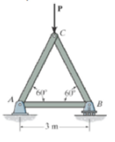
Prob. F6-4

Trending nowThis is a popular solution!

Learn your wayIncludes step-by-step video

Chapter 6 Solutions
Engineering Mechanics: Statics, Student Value Edition; Modified Mastering Engineering with Pearson eText -- Standalone Access Card -- for Engineering Mechanics: Statics (14th Edition)
Additional Engineering Textbook Solutions
Automotive Technology: Principles, Diagnosis, And Service (6th Edition) (halderman Automotive Series)
Mechanics of Materials (10th Edition)
Engineering Mechanics: Statics & Dynamics (14th Edition)
Thinking Like an Engineer: An Active Learning Approach (4th Edition)
Mechanics of Materials
Engineering Mechanics: Dynamics (14th Edition)


- Determine the greatest force P that can be applied to the truss so that none of the members are subjected to a force exceeding either 4.5 kN in tension or 3 kN in compression.arrow_forwardThe rigid bar is supported by the two short white spruce wooden posts and a spring. If each of the posts has an unloaded length of 1 m and a cross-sectional area of 600 mm2, and the spring has a stiffness of k = 2 MN >m and an unstretched length of 1.02 m, determine the force in each post after the load is applied to the bar.arrow_forwardIf the gap between C and the rigid wall at D is initially 0.15 mm, determine the support reactions at A and D when the force P = 200 kN is applied. The assembly is made of solid A-36 steel cylinders.arrow_forward
- Determine the force in the members' AB, AE, AF, BC, BE, CD, CE, DE, EF, and state if each member is in tension or compression. P1=9kN and P2=14kNarrow_forwardDetermine the force in member 2 of the assembly as shown if the support at joint 1 settles downward 25 mm. Take AE = 8(103) kN.arrow_forwardQ1:a- Identify the zero-force members in the truss. b- Determine the force in each member of the truss using Method of Joints. State if the members are in tension or compression. F = 7 kNarrow_forward
- Determine the forces on the DF, EF and EG members, indicating whether they are traction or compression. Use the section method.H = 83arrow_forwardDetermine the forces in members BJ, BI, CI, CH, DG, DH, and EG of the loaded truss. All triangles are 45°-45°-90°. The forces are positive if in tension, negative if in compression.arrow_forwardDetermine the force in members FG, FH, and HG of the truss which serves to support the deck of a bridge if P1 = 50kN, P2 = 20kN and P3 = 10kN. State if these members are in tension or compression.arrow_forward
- The mobile crane is symmetrically supported by two outriggers at A and B to relieve the suspension of the vehicle on which it sits and to provide extra stability. Determine the vertical reactions at each of the two outriggers as a function of boom angle when the boom is carrying a 1.2 Mg load and the crane and truck have a combined mass of 18 Mg and the boom has a mass of 2 Mg. 0 = 45°arrow_forwardDetermine the tension developed in cables OD and OB and the strut OC, required to support the 50-kg crate. The spring OA has an unstretched length of 0.8 m and stiffness kOA = 1.2 kN/m The force in the strut acts along the axis of the strut.arrow_forwardDetermine the force in each member of the loaded truss. The forces are positive if in tension, negative if in compression. Assume F1 = 3600 lb, F2 = 3200 lb, a=4.1 ft, b=6.6 ft, c=2.2 ft, d=3.2 ftarrow_forward
 Elements Of ElectromagneticsMechanical EngineeringISBN:9780190698614Author:Sadiku, Matthew N. O.Publisher:Oxford University Press
 Mechanics of Materials (10th Edition)Mechanical EngineeringISBN:9780134319650Author:Russell C. HibbelerPublisher:PEARSON
 Thermodynamics: An Engineering ApproachMechanical EngineeringISBN:9781259822674Author:Yunus A. Cengel Dr., Michael A. BolesPublisher:McGraw-Hill Education
 Control Systems EngineeringMechanical EngineeringISBN:9781118170519Author:Norman S. NisePublisher:WILEY
 Mechanics of Materials (MindTap Course List)Mechanical EngineeringISBN:9781337093347Author:Barry J. Goodno, James M. GerePublisher:Cengage Learning
 Engineering Mechanics: StaticsMechanical EngineeringISBN:9781118807330Author:James L. Meriam, L. G. Kraige, J. N. BoltonPublisher:WILEY