
Concept explainers
Videos
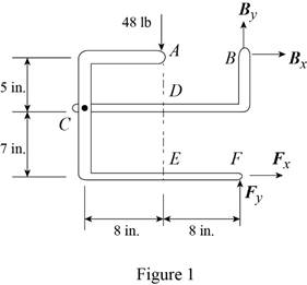
The 48-lb load can be moved along the line of action shown and applied at A, D, or E. Determine the components of the reactions at B and F if the 48-lb load is applied (a) at A, (b) at D, (c) at E.
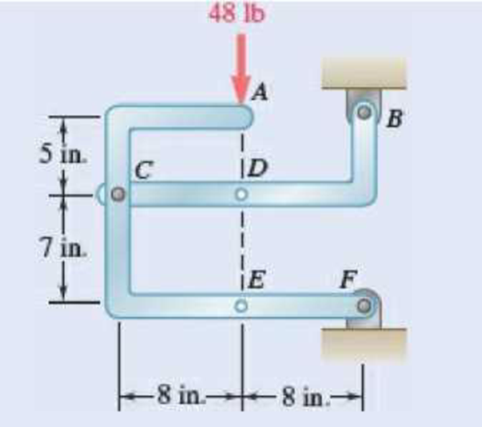
Fig. P6.88 and P6.89
SOLUTION
Free body: Entire frame:
The following analysis is valid for (a), (b) and (c) since the position of the load along its line of action is immaterial.
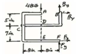
 ∑MF = 0: (48 lb)(8 in.) − Bx (12 in.) = 0
Bx = 32 lb Bx = 32 lb →
 ∑Fx = 0: 32 lb + Fx = 0
Fx = −32 lb Fx = 32 lb ←
+↑ ∑Fy = 0: By + Fy − 48 lb = 0 (1)
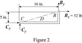
a) Load applied at A.
Free body: Member CDB
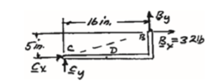
CDB is a two-force member. Thus, the reaction at B must be directed along BC.
From Eq. (1): 10 lb + Fy − 48 lb = 0
Fy = 38 lb Fy = 38 lb ↑
Thus reactions are:
Bx = 32.0 lb →, By = 10.00 lb ↑
Fx = 32.0 lb ←, Fy = 38.00 lb ↑
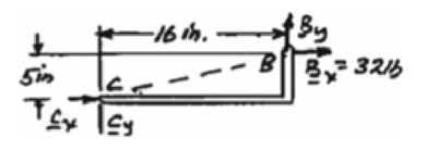
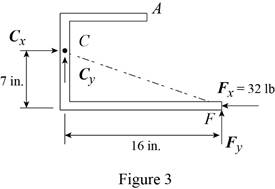
(b) Load applied at D.
Free body: Member ACF.
ACF is a two-force member. Thus, the reaction at F must be directed along CF.
From Eq. (1): By + 14 lb – 48 lb = 0
By = 34 lb, By = 34 lb ↑
Thus, reactions are:
Bx = 32.0 lb ←, By = 34.00 lb ↑
Fx = 32.0 lb →, Fy = 14.00 lb ↑
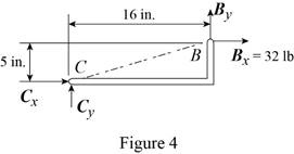
(c) Load applied at E.
Free body: Member CDB.
This is the same free body as in Part (a).
Reactions are same as (a)
(a)
The components of reaction at
Answer to Problem 6.88P
The components of reaction at
Explanation of Solution
The arrangement is shown in Fig. P6.88. The free-body diagram of the entire frame is given in Figure 1.
Write the expressions for equilibrium for the given system using the conditions on moments
The counter clockwise moments at
The sum of
The sum of
The load is applied at
Conclusion:
Apply the condition in equation (I) to the free-body diagram in Figure 1 and solve for
Apply the condition in equation (II) to the free-body diagram in Figure 1 and solve for
Apply the condition in equation (III) to the free-body diagram in Figure 1.
From the free-body diagram in Figure 2, write the expression connecting the components of the reaction
Substitute
Substitute
Therefore, the components of reaction at
(b)
The components of reaction at
Answer to Problem 6.88P
The components of reaction at
Explanation of Solution
The
The load is applied at
Conclusion:
From the free-body diagram in Figure 3, write the expression connecting the components of the reaction
Substitute
Substitute
Therefore, the components of reaction at
(c)
The components of reaction at
Answer to Problem 6.88P
The components of reaction at
Explanation of Solution
The
The load is applied at
Conclusion:
The free-body diagram of the member
Therefore, the components of reaction at
Want to see more full solutions like this?
Chapter 6 Solutions
Vector Mechanics for Engineers: Statics


- The L-shaped member ACB is supported by a pin and bracket at C and by an inextensible cord attached at A and B and passing over a frictionless pulley at D. The tension may be assumed to be the same in portions AD and BD of the cord. If the magnitudes of the forces applied at A and B are, respectively, P = 25 lb and Q = 0, determine (a) the tension in the cord, (b) the reaction at Carrow_forwardTwo tape spools are attached to an axle supported by bearings at A and D . The radius of spool B is 1.5 in. and the radius of spool C is 2 in. Knowing that TB= 20 lb and that the system rotates at a constant rate, draw the free-body diagram needed to determine the reactions at A and D . Assume that the bearing at A does not exert any axial thrust and neglect the weights of the spools and axle.arrow_forwardThe cab and motor units of the front-end loader shown are connected by a vertical pin located 2 m behind the cab wheels. The distance from C to D is 1 m. The center of gravity of the 300-kN motor unit is located at Gm , while the centers of gravity of the 100-kN cab and 75-kN load are located, respectively, at Gc and GI. . Knowing that the machine is at rest with its brakes released, determine (a) the reactions at each of the four wheels, (b) the forces exerted on the motor unit at C and D.arrow_forward
- Member ABC is supported by a pin and bracket at B and by an inextensible cord attached at A and C and passing over a frictionless pulley at D. The tension may be assumed to be the same in portions AD and CD of the cord. For the loading shown and neglecting the size of the pulley, determine the tension in the cord and the reaction at B.arrow_forwardThe T-shaped bracket shown is supported by a small wheel at E and pegs at C and D . Neglecting the effect of friction, determine (a) the smallest value of 0 for which the equilibrium of the bracket is maintained, (b) the corresponding reactions at C, D, and E.arrow_forwardA 5 x 8-ft sign of uniform density weighs 270 lb and is supported by a ball-and-socket joint at A and by two cables. Determine the tension in each cable and the reaction at A.arrow_forward
- A force P of magnitude 90 lb is applied to member ACDE that is supported by a frictionless pin at D and by the cable ABE . Since the cable passes over a small pulley at B , the tension may be assumed to be the same in portions AB and BE of the cable. For the case when a= 3 in., determine (a) the tension in the cable, (b) the reaction at D.arrow_forwardA uniform rod AB of length 2R rests inside a hemispherical bowl of radius R as shown. Neglecting friction, determine the angle 0 corresponding to equilibrium.arrow_forward4.7 A hand truck is used to move a compressed-air cylinder. Knowing that the combined weight of the truck and cylinder is 180 lb. determine (a) the vertical force P that should be applied to the handle to maintain the cylinder in the position shown, (b) the corresponding reaction at each of the two wheels.arrow_forward
- The maximum allowable value of each of the reactions is 180 N. Neglecting the weight of the beam, determine the range of the distance d for which the beam is safe.arrow_forwardA light bar AD is suspended from a cable BE and supports a 50-lb block at C. The ends A and D of the bar are in contact with frictionless vertical walls. Determine the tension in cable BE and the reactions at A and D.arrow_forwardA uniform rod AB with a length of l and weight of W is suspended from two cords AC and BC of equal length. Determine the angle 0 corresponding to the equilibrium position when a couple M is applied to the rod.arrow_forward
 Elements Of ElectromagneticsMechanical EngineeringISBN:9780190698614Author:Sadiku, Matthew N. O.Publisher:Oxford University Press
 Mechanics of Materials (10th Edition)Mechanical EngineeringISBN:9780134319650Author:Russell C. HibbelerPublisher:PEARSON
 Thermodynamics: An Engineering ApproachMechanical EngineeringISBN:9781259822674Author:Yunus A. Cengel Dr., Michael A. BolesPublisher:McGraw-Hill Education
 Control Systems EngineeringMechanical EngineeringISBN:9781118170519Author:Norman S. NisePublisher:WILEY
 Mechanics of Materials (MindTap Course List)Mechanical EngineeringISBN:9781337093347Author:Barry J. Goodno, James M. GerePublisher:Cengage Learning
 Engineering Mechanics: StaticsMechanical EngineeringISBN:9781118807330Author:James L. Meriam, L. G. Kraige, J. N. BoltonPublisher:WILEY