
Concept explainers
Videos
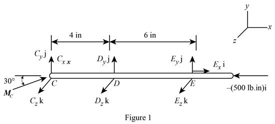
Two shafts AC and CF, which lie in the vertical xy plane, are connected by a universal joint at C. The bearings at B and D do not exert any axial force. A couple with a magnitude of 500 lb·in. (clockwise when viewed from the positive x axis) is applied to shaft CF at F. At a time when the arm of the crosspiece attached to shaft CF is horizontal, determine (a) the magnitude of the couple that must be applied to shaft AC at A to maintain equilibrium, (b) the reactions at B, D, and E. (Hint: The sum of the couples exerted on the crosspiece must be zero.)

Fig. P6.161
(a)
The magnitude of the couple that must be applied to shaft
Answer to Problem 6.161P
The magnitude of the couple that must be applied to shaft
Explanation of Solution
Take all vectors along the
The free body diagram of the shaft
Here,
At equilibrium total moment will be zero.
Write the expression for the equilibrium moment about
Here,
The moment along the
From free body diagram in figure1, write the complete equilibrium expression of moment about
 (II)
(II)
Here,
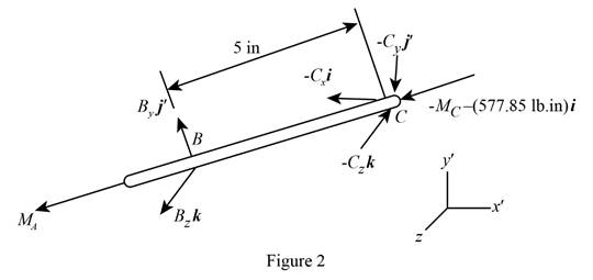
The free body diagram of the shaft
Here,
Write the expression for the equilibrium moment about
Here,
From free body diagram in figure2, write the complete equilibrium expression of moment about
Here,
Calculation:
Rearrange equation (II) to get
Equate coefficient of
Therefore, the magnitude of the couple that must be applied to shaft
(b)
The reaction at
Answer to Problem 6.161P
The reaction at
Explanation of Solution
From free body diagram in figure2, write the complete equilibrium expression of moment about
Here,
Since the net force at the shaft
Using free body diagram in figure1, apply the equilibrium condition for moment about
Here,
From figure1, write the complete expression of moment
Since net force at shaft
Calculation:
Equate coefficient of
Equate coefficient of
Therefore
Substitute
Equate coefficient of
Equate coefficient of
Equate coefficient of
Therefore, net reaction at
Equate coefficient of
Substitute
Therefore, total reaction at
Therefore, the reaction at
Want to see more full solutions like this?
Chapter 6 Solutions
EBK VECTOR MECHANICS FOR ENGINEERS: STA


- H.W: A frame ABC is supported in part by cable DBE that passes through a frictionless ring at B. Knowing that the tension in the cable is 385 N, determine (a)- the resultant ( R) of the forees as a vector which exerted by the cables on the support at D and E, (b)- the angles between R and each of the coordinate axes. Answer: 210 ma R= Fan + Fn =-(375 N)i + (455 N)j-(460 N)k e, =120.1° e, = 52.5° 510 m 400 am 0. = 128.0° IB 0marrow_forwardThe force P has a magnitude of 250 N and is applied at the end C of a 500-mm rod AC attached to a bracket at A and B. Assuming α =30° and β=60°, replace P with (a) an equivalent force-couple system at B, (b) an equivalent system formed by two parallel forces applied at A and B.arrow_forward2.81 The steering column of the rack-and-pinion steering mechanism lies in the z-plane. The tube AB of the steering gear is attached to the automobile chassis at A and B. When the steering wheel is turned, the assembly is subjected to the four couples shown: the 3-N - m couple applied by the driver to the steering wheel, two 1.8-N - m couples (one at each wheel), and the couple formed by the two forces of magnitude Facting at A and B. If the resultant couple acting on the steering mechanism is zero, determine Fand the angle e (the magnitude and direction of the bearing reactions). 3N-m 360 mm 1.8N-m 1.8 N-m Figure P2.81arrow_forward
- Determine the magnitude of the moment of the force F about point O. F = 120 b 1ft 4 ft 2 ft 4 ft А. Мо — 447 lb — ft | %3D C. M, = 436 lb – ft D. M, = 459 lb – ft |arrow_forwardA control rod AB is fixed with a pin connection at B. The rod is 26 in long and is at an angle of 60 degrees from the positive x-axis. A 11.9 lb force F is applied to the end of the control rod (point A) down and to the right, at an angle of α from the rod. Knowing that it creates a 253.4 in lb clockwise moment about point B, determine angle α and the perpendicular distance between the line of action of force F and point B.arrow_forwardProblem (1):-Determine the resultant of coplanar force system of the fig.( 1) and locate it with respect to point (A). 90N 100N .m 2m 3m 90N 200N 3m 4 4m 3 4m 3m Fig.(1) Problem2 / Determine the resultant of the force system of the fig. (2) and locate it with respect to point (A). 200N 360N 3m 500N 3 2m A 200N im 5m Fig.(2) Problem 3/ Determine the resultant of the resultant of the force system shown in fig.(3) and locate it with respect to point (A). 4m 5m 3m l, 4m 40N 30N 20 N Fig.(3)arrow_forward
- Five separate force-couple systems act at the corners of a piece of sheet metal that has been bent into the shape shown. Determine which of these systems is equivalent to a force F = (10 lb)i and a couple of moment M = (15 lb·ft)j + (15 lb·ft) k located at the origin.arrow_forwardAn angular bracket shown is acted upon by forces and a couple applied in the direction and location indicated. Locate the resultant (distance) from point A. A, H-90 N K W=140 N 200 mm 200 mm 100 mm 40° 400 mm P=80 N √√3 F-200 N W= 70Narrow_forwardIn opening a door which is equipped with a heavy- duty return mechanism, a person exerts a force P of magnitude 8 lb as shown. Force P and the normal n to the face of the door lie in a vertical plane. Ex- press P as a vector and determine the angles 0, 0y, and 0, which the line of action of P makes with the positive x-, y-, and z-axes. 40" P. 30° y 20°arrow_forward
- A 120-lb force is applied to the brake pedal at A. Knowing that the distance AB is 8 in. , determine the moment 3.1 N20 lb of the force about B when a is 30°. 750 50°arrow_forwardQ6 A machine component is subjected to the forces and couples shown. The component is to be held in place by a single rivet that can resist a force but not a couple. The location of the rivet hole on line FG and line GH is... 120 N 240 mm 200 N 70° 15 H 50 mm 42 Nm 180 N 520 mm C 60 N 180 mm F |B -50 mm 40 Nm iG A 50 mm 640 mmarrow_forwardForce F shown has a magnitude = 8 kN. The magniude of the moment of . :about the z-axis i 4 m F | 6 m y اخترأحد الخيارات kN.m 60 O kN.m 40 O kN.m 0 O kN.m 48 O kN.m 32arrow_forward
 Elements Of ElectromagneticsMechanical EngineeringISBN:9780190698614Author:Sadiku, Matthew N. O.Publisher:Oxford University Press
 Mechanics of Materials (10th Edition)Mechanical EngineeringISBN:9780134319650Author:Russell C. HibbelerPublisher:PEARSON
 Thermodynamics: An Engineering ApproachMechanical EngineeringISBN:9781259822674Author:Yunus A. Cengel Dr., Michael A. BolesPublisher:McGraw-Hill Education
 Control Systems EngineeringMechanical EngineeringISBN:9781118170519Author:Norman S. NisePublisher:WILEY
 Mechanics of Materials (MindTap Course List)Mechanical EngineeringISBN:9781337093347Author:Barry J. Goodno, James M. GerePublisher:Cengage Learning
 Engineering Mechanics: StaticsMechanical EngineeringISBN:9781118807330Author:James L. Meriam, L. G. Kraige, J. N. BoltonPublisher:WILEY