
Concept explainers
Videos
Two shafts AC and CF, which lie in the vertical xy plane, are connected by a universal joint at C. The bearings at B and D do not exert any axial force. A couple with a magnitude of 500 lb·in. (clockwise when viewed from the positive x axis) is applied to shaft CF at F. At a time when the arm of the crosspiece attached to shaft CF is horizontal, determine (a) the magnitude of the couple that must be applied to shaft AC at A to maintain equilibrium, (b) the reactions at B, D, and E. (Hint: The sum of the couples exerted on the crosspiece must be zero.)
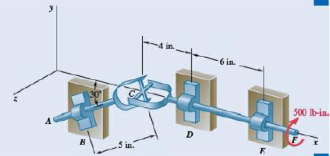
Fig. P6.161
*6.162 Solve Prob. 6.161 assuming that the arm of the crosspiece attached to shaft CF is vertical.
(a)
The magnitude of the couple that must be applied to shaft
Answer to Problem 6.162P
The magnitude of the couple that must be applied to shaft
Explanation of Solution
Take all vectors along the
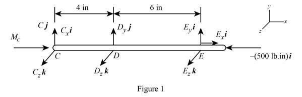
The free body diagram of the shaft
Here,
At equilibrium total moment will be zero.
Write the expression for the equilibrium moment about
Here,
The moment along the
From free body diagram in figure1, write the complete equilibrium expression of moment about
 (II)
(II)
Here,
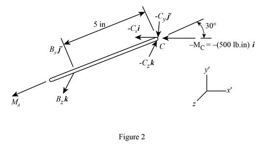
The free body diagram of the shaft
Here,
Write the expression for the equilibrium moment about
Here,
Resolve
From free body diagram in figure2, write the complete equilibrium expression of moment about
Here,
Calculation:
Rearrange equation (II) to get
Equate coefficient of
Therefore, the magnitude of the couple that must be applied to shaft
(b)
The reaction at
Answer to Problem 6.162P
The reaction at
Explanation of Solution
From free body diagram in figure2, write the complete equilibrium expression of moment about
Here,
Since the net force at the shaft
Using free body diagram in figure1, apply the equilibrium condition for moment about
Here,
From figure1, write the complete expression of moment
Since net force at shaft
Calculation:
Equate coefficient of
Equate coefficient of
Therefore,
Substitute
Equate coefficient of
Equate coefficient of
Equate coefficient of
Therefore, net reaction at
Substitute
Equate coefficient of
Therefore, total reaction at
Therefore, the reaction at
Want to see more full solutions like this?
Chapter 6 Solutions
Vector Mechanics for Engineers: Statics


- Show that, when a rigid body rotates about a fixed axis through O perpendicular to the body, the system of the momenta of its particles is equivalent to a single vector of magnitude mrw, perpendicular to the line OG, and applied to a point P on this line, called the center of percussion, at a distance GP=k2/r from the mass center of the body.arrow_forwardA shaft carries four masses, B, C, and D of magnitude 200 kg, 300 kg, 400 kg, and 200 kg respectively and revolving at radii 80 mm, 70 mm, 60 mm, and 80 mm in planes measured from A at 300 mm, 400 mm and 700 mm. The angles between the cranks measured anticlockwise are A to B 45º, B to C 70º, and C to D 120º. the balancing masses are to be placed in planes X and Y. The distance between the planes A and X is 100 mm, between X and Y is 400 mm and between Y and D is 200 mm. If the balancing masses revolve at a radius of 100 mm, find their magnitude and angular positions.arrow_forwardPractice Problem 2.4.7:Knowing that theforces P and Q are equivalent to a singleforce R that passes through point A,determine P.arrow_forward
- The cab and motor units of the front-end loader shown are connected by a vertical pin located 2 m behind the cab wheels. The distance from C to D is 1 m. The center of gravity of the 300-kN motor unit is located at Gm, while the centers of gravity of the 100-kN cab and 75-kN load are located, respectively, at Gc and Gl. Knowing that the front-end loader is at rest with its brakes released, determine(a) the reactions at each of the four wheels, (b) the forces exertedon the motor unit at C and D.arrow_forwardA single-acting cylinder working in traction under a pressure of60 psig has a return spring with a force of 15 lbs. Knowing that the diameter ofthe rod is ¼ in. and that of the piston is 1 in., what is the force developedby this cylinder? [Answer:29.4 lbs]arrow_forwardKnowing that the tension in cable AC is 300 lb, determine the smallest angle between cable AC and the boom AB. The smallest angle is?arrow_forward
- A force of 90 N is applied on a lever AB as shown in the figure. Knowing that the lever is 225 mm long and that the moment of force in relation to point B is 13.5 N.m clockwise, determine the value of α.arrow_forwardA control rod AB is fixed with a pin connection at B. The rod is 26 in long and is at an angle of 60 degrees from the positive x-axis. A 11.9 lb force F is applied to the end of the control rod (point A) down and to the right, at an angle of α from the rod. Knowing that it creates a 253.4 in lb clockwise moment about point B, determine angle α and the perpendicular distance between the line of action of force F and point B.arrow_forwardA 20-lb force is applied to the control rod AB as shown. Knowing that the length of the rod is 9 in. and that the moment of the force about B is 120lb.in. clockwise, determine the value of α.arrow_forward
- A 160-lb force P is applied at point A of a structural member.Replace P with (a) an equivalent force-couple system at C, (b) an equivalent system consisting of a vertical force at B and a second force at D.arrow_forwardAn 8-m long cantilever beam is loaded with vertical forces A = 60 kN and B = 108 kN, separated by a distance d = 5.6 m, as shown. Replace the two forces with a single equivalent force R and determine the distance x-bar (x¯) from the left end of the beam to the line of action of R.arrow_forwardA uniform rod AB of length 2R rests inside a hemispherical bowl of radius R as shown. Neglecting friction, determine the angle 0 corresponding to equilibrium.arrow_forward
 Elements Of ElectromagneticsMechanical EngineeringISBN:9780190698614Author:Sadiku, Matthew N. O.Publisher:Oxford University Press
 Mechanics of Materials (10th Edition)Mechanical EngineeringISBN:9780134319650Author:Russell C. HibbelerPublisher:PEARSON
 Thermodynamics: An Engineering ApproachMechanical EngineeringISBN:9781259822674Author:Yunus A. Cengel Dr., Michael A. BolesPublisher:McGraw-Hill Education
 Control Systems EngineeringMechanical EngineeringISBN:9781118170519Author:Norman S. NisePublisher:WILEY
 Mechanics of Materials (MindTap Course List)Mechanical EngineeringISBN:9781337093347Author:Barry J. Goodno, James M. GerePublisher:Cengage Learning
 Engineering Mechanics: StaticsMechanical EngineeringISBN:9781118807330Author:James L. Meriam, L. G. Kraige, J. N. BoltonPublisher:WILEY