
EBK MECHANICS OF MATERIALS
7th Edition
ISBN: 9780100257061
Author: BEER
Publisher: YUZU
expand_more
expand_more
format_list_bulleted
Videos
Textbook Question
Chapter 6.5, Problem 29P
The built-up timber beam shown is subjected to a vertical shear of 1200 lb. Knowing that the allowable shearing force in the nails is 75 lb, determine the largest permissible spacing s of the nails.
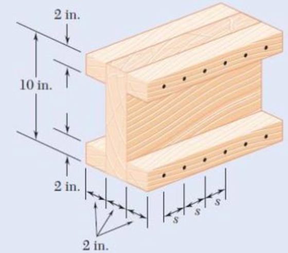
Fig. p6.29
Expert Solution & Answer

Trending nowThis is a popular solution!

Students have asked these similar questions
50 mm
100 mm
50 mm
150 mm
50 men
Three boards, each 50 mm thick, are nailed together to form a beam
that is subjected to a 1200-N vertical shear. Knowing that the
allowable shearing force in each nail is 600 N, determine the largest
permissible spactags between the nails.
A beam consists of five planks of 1.5 x 6-in. cross section connected by steel bolts with a longitudinal spacing of 9 in. Knowing that the shear in the beam is vertical and equal to 2000 lb and that the allow-able average shearing stress in each bolt is 7500 psi, determine the smallest permissible bolt diameter that can be used.
The American Standard rolled-steel beam shown has been reinforced by attaching to it two 16 x 200-mm plates, using 18-mm-diameter bolts spaced longitudinally every 120 mm. Knowing that the average allowable shearing stress in the bolts is 90 MPa, determine the largest permissible vertical shearing force.
Chapter 6 Solutions
EBK MECHANICS OF MATERIALS
Ch. 6.2 - Three full-size 50 100-mm boards are nailed...Ch. 6.2 - For the built-up beam of Prob. 6.1, determine the...Ch. 6.2 - Three boards, each 2 in. thick, are nailed...Ch. 6.2 - A square box beam is made of two 20 80-mm planks...Ch. 6.2 - The American Standard rolled-steel beam shown has...Ch. 6.2 - The beam shown is fabricated by connecting two...Ch. 6.2 - A column is fabricated by connecting the...Ch. 6.2 - The composite beam shown is fabricated by...Ch. 6.2 - 6.9 through 6.12 For beam and loading shown,...Ch. 6.2 - 6.9 through 6.12 For beam and loading shown,...
Ch. 6.2 - 6.9 through 6.12 For beam and loading shown,...Ch. 6.2 - 6.9 through 6.12 For beam and loading shown,...Ch. 6.2 - 6.13 and 6.14 For a beam having the cross section...Ch. 6.2 - 6.13 and 6.14 For a beam having the cross section...Ch. 6.2 - For a timber beam having the cross section shown,...Ch. 6.2 - Two steel plates of 12 220-mm rectangular cross...Ch. 6.2 - Two W8 31 rolled sections may be welded at A and...Ch. 6.2 - For the beam and. loading shown, determine the...Ch. 6.2 - Fig. P6.19 6.19 A timber beam AB of length L and...Ch. 6.2 - A timber beam AB of Length L and rectangular cross...Ch. 6.2 - 6.21 and 6.22 For the beam and loading shown,...Ch. 6.2 - 6.21 and 6.22 For the beam and loading shown,...Ch. 6.2 - 6.23 and 6.24 For the beam and loading shown,...Ch. 6.2 - 6.23 and 6.24 For the beam and loading shown,...Ch. 6.2 - 6.25 through 6.28 A beam having the cross section...Ch. 6.2 - 6.25 through 6.28 A beam having the cross section...Ch. 6.2 - Prob. 27PCh. 6.2 - 6.25 through 6.28 A beam having the cross section...Ch. 6.5 - The built-up timber beam shown is subjected to a...Ch. 6.5 - The built-up beam shown is made by gluing together...Ch. 6.5 - The built-up beam was made by gluing together...Ch. 6.5 - Several wooden planks are glued together to form...Ch. 6.5 - The built-up wooden beam shown is subjected to a...Ch. 6.5 - Knowing that a W360 122 rolled-steel beam is...Ch. 6.5 - 6.35 and 6.36 An extruded aluminum beam has the...Ch. 6.5 - 6.35 and 6.36 An extruded aluminum beam has the...Ch. 6.5 - Knowing that a given vertical shear V causes a...Ch. 6.5 - The vertical shear is 1200 lb in a beam having the...Ch. 6.5 - The vertical shear is 1200 lb in a beam having the...Ch. 6.5 - 6.40 and 6.47 The extruded aluminum beam has a...Ch. 6.5 - Prob. 41PCh. 6.5 - Prob. 42PCh. 6.5 - Three planks are connected as shown by bolts of...Ch. 6.5 - A beam consists of three planks connected as shown...Ch. 6.5 - A beam consists of five planks of 1.5 6-in. cross...Ch. 6.5 - Four L102 102 9.5 steel angle shapes and a 12 ...Ch. 6.5 - A plate of 14-in. thickness is corrugated as shown...Ch. 6.5 - Prob. 48PCh. 6.5 - An extruded beam has the cross section shown and a...Ch. 6.5 - Prob. 50PCh. 6.5 - The design of a beam calls for connecting two...Ch. 6.5 - The cross section of an extruded beam is a hollow...Ch. 6.5 - Prob. 53PCh. 6.5 - Prob. 54PCh. 6.5 - Prob. 55PCh. 6.5 - 6.56 and 6.57 A composite beam is made by...Ch. 6.5 - 6.56 and 6.57 A composite beam is made by...Ch. 6.5 - Prob. 58PCh. 6.5 - Prob. 59PCh. 6.5 - Prob. 60PCh. 6.6 - 6.61 through 6.64 Determine the location of the...Ch. 6.6 - 6.61 through 6.64 Determine the location of the...Ch. 6.6 - 6.61 through 6.64 Determine the location of the...Ch. 6.6 - Prob. 64PCh. 6.6 - 6.65 through 6.68 An extruded beam has the cross...Ch. 6.6 - 6.65 through 6.68 An extruded beam has the cross...Ch. 6.6 - 6.65 through 6.68 An extruded beam has the cross...Ch. 6.6 - 6.65 through 6.68 An extruded beam has the cross...Ch. 6.6 - 6.69 through 6.74 Determine the location of the...Ch. 6.6 - Prob. 70PCh. 6.6 - Prob. 71PCh. 6.6 - Prob. 72PCh. 6.6 - Prob. 73PCh. 6.6 - Prob. 74PCh. 6.6 - Prob. 75PCh. 6.6 - 6.75 and 6.76 A thin-walled beam has the cross...Ch. 6.6 - 6.77 and 6.78 A thin-walled beam of uniform...Ch. 6.6 - Prob. 78PCh. 6.6 - Prob. 79PCh. 6.6 - Prob. 80PCh. 6.6 - Prob. 81PCh. 6.6 - Prob. 82PCh. 6.6 - Prob. 83PCh. 6.6 - Prob. 84PCh. 6.6 - Prob. 85PCh. 6.6 - Solve Prob. 6.85, assuming that the thickness of...Ch. 6.6 - Prob. 87PCh. 6.6 - Prob. 88PCh. 6 - Three boards are nailed together to form the beam...Ch. 6 - For the beam and loading shown, consider section...Ch. 6 - For the wide-flange beam with the loading shown,...Ch. 6 - For the beam and loading shown, consider section...Ch. 6 - The built-up timber beam is subjected to a 1500-lb...Ch. 6 - Knowing that a given vertical shear V causes a...Ch. 6 - Three planks are connected as shown by bolts of...Ch. 6 - Three 1 18-in. steel plates are bolted to four L6...Ch. 6 - The composite beam shown is made by welding C200 ...Ch. 6 - Prob. 98RPCh. 6 - A thin-walled beam of uniform thickness has the...Ch. 6 - Determine the location of the shear center O of a...
Knowledge Booster


Learn more about
Need a deep-dive on the concept behind this application? Look no further. Learn more about this topic, mechanical-engineering and related others by exploring similar questions and additional content below.Similar questions
- Three boards, each of 1.5 x3.5-in. rectangular cross section, are nailed together to form a beam that is subjected to a vertical shear of 250 lb. Knowing that the spacing between each pair of nails is 2.5 in., determine the shearing force in each nail.arrow_forwardThe thin-walled extruded beam shown is made of aluminum and has a uni-form 3-mm wall thickness. Knowing that the shear in the beam is 5 kN, deter-mine (a) the shearing stress at point A, (b) the maximum shearing stress in the beam. Note: The dimensions given are to lines midway between the outer and inner surfaces of the beam.arrow_forwardL/4 D L/2 LA B A timber beam AB of length L and rectangular cross section carries a uniformly distributed load w and is supported as shown. (a) Show that the ratio of the maximum values of the shearing and normal stresses in the beam is equal to 2h/L, where h and L are, respectively, the depth and the length of the beam. (b) Determine the depth h and the width b of the beam, knowing that L = 5 m, w = 8 kN/m, Tm = 1.08 MPa, and om = 12 MPa.arrow_forward
- Two plates, eachin. thick, are used to splice a plastic strip as shown. Knowing that the ultimate shearing stress of the bonding between the surfaces is 130 psi, determine the factor of safety with respect to shear when P = 385 lb. in. in. 2-in. in. P The factor of safety with respect to shear isarrow_forwardShow all workarrow_forwardSeveral wooden planks are glued together to form the box beam shown. Knowing that the beam is subjected to a vertical shear of 3 kN, deter-mine the average shearing stress in the glued joint (a) at A, (b) at B.arrow_forward
- 2. Link AB, of width b 5 50 mm and thickness t 5 6 mm, is used to support the end of a horizontal beam. Knowing that the average normal stress in the link is 2140 MPa, and that the average shearing stress in each of the two pins is 80 MPa, determine (a) the diameter d of the pins, (b) the average bearing stress in the link.arrow_forwardTwo W8 x 31 rolled sections can be welded at A and B in either of the two ways shown in order to form a composite beam. Knowing that for each weld the allowable horizontal shearing force is 3000 lb per inch of weld, determine the maximum allowable vertical shear in the composite beam for each of the two arrangements shown.arrow_forwardMechanics of deformable bodiesarrow_forward
- Three 1 x 18-in. steel plates are bolted to four L6 x 6 x 1 angles to form a beam with the cross section shown. The bolts have a 78-in. diameter and are spaced longitudinally every 5 in. Knowing that the allowable average shearing stress in the bolts is 12 ksi, determine the largest permissible vertical shear in the beam. (Given: Ix= 6123 in4.)arrow_forwardThe extruded aluminum beam shown has a uniform wall thickness of 1/8 in. Knowing that the vertical shear in the beam is 2 kips, determine the corresponding shearing stress at each of the five points indicated.arrow_forwardHomework A timber beam AB of length L and rectangular cross section carries a single concentrated load P at its midpoint C. (a) Show that the ratio Tm/Tm of the maximum values of the shearing and normal stresses in the beam is equal to h/2L, where h and L are, respectively, the depth and the length of the beam. (b) Determine the depth h and the width b of the beam, knowing that L = 2 m, P = 40 kN, 7m = 960 kPa, and om = 12 MPa. |P L/2 - - L/2· A Вarrow_forward
arrow_back_ios
SEE MORE QUESTIONS
arrow_forward_ios
Recommended textbooks for you
 Elements Of ElectromagneticsMechanical EngineeringISBN:9780190698614Author:Sadiku, Matthew N. O.Publisher:Oxford University Press
 Mechanics of Materials (10th Edition)Mechanical EngineeringISBN:9780134319650Author:Russell C. HibbelerPublisher:PEARSON
 Thermodynamics: An Engineering ApproachMechanical EngineeringISBN:9781259822674Author:Yunus A. Cengel Dr., Michael A. BolesPublisher:McGraw-Hill Education
 Control Systems EngineeringMechanical EngineeringISBN:9781118170519Author:Norman S. NisePublisher:WILEY
 Mechanics of Materials (MindTap Course List)Mechanical EngineeringISBN:9781337093347Author:Barry J. Goodno, James M. GerePublisher:Cengage Learning
 Engineering Mechanics: StaticsMechanical EngineeringISBN:9781118807330Author:James L. Meriam, L. G. Kraige, J. N. BoltonPublisher:WILEY
Elements Of Electromagnetics
Mechanical Engineering
ISBN:9780190698614
Author:Sadiku, Matthew N. O.
Publisher:Oxford University Press
Mechanics of Materials (10th Edition)
Mechanical Engineering
ISBN:9780134319650
Author:Russell C. Hibbeler
Publisher:PEARSON
Thermodynamics: An Engineering Approach
Mechanical Engineering
ISBN:9781259822674
Author:Yunus A. Cengel Dr., Michael A. Boles
Publisher:McGraw-Hill Education
Control Systems Engineering
Mechanical Engineering
ISBN:9781118170519
Author:Norman S. Nise
Publisher:WILEY
Mechanics of Materials (MindTap Course List)
Mechanical Engineering
ISBN:9781337093347
Author:Barry J. Goodno, James M. Gere
Publisher:Cengage Learning
Engineering Mechanics: Statics
Mechanical Engineering
ISBN:9781118807330
Author:James L. Meriam, L. G. Kraige, J. N. Bolton
Publisher:WILEY
Mechanics of Materials Lecture: Beam Design; Author: UWMC Engineering;https://www.youtube.com/watch?v=-wVs5pvQPm4;License: Standard Youtube License