
Mechanics of Materials, Student Value Edition (10th Edition)
10th Edition
ISBN: 9780134321189
Author: Russell C. Hibbeler
Publisher: PEARSON
expand_more
expand_more
format_list_bulleted
Concept explainers
Videos
Textbook Question
Chapter 6.5, Problem 6.111P
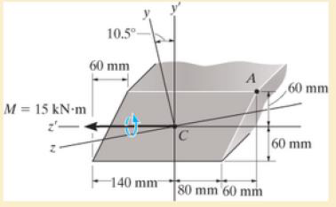
For the section, lz’ = 31.7(10-5) m4, lY’ = 114(10-5) m4, Iy,z' = -15.8(10-6) m4. Using the techniques outlined in Appendix A, the member’s cross-sectional area has principal moments of inertia of lz = 28.8(10-6) m4 and ly = 117(10-6) m4, calculated about the principal axes of inertia y and z, respectively. If the section is subjected to the moment M = 15 kN · m, determine the stress at point A using Eq. 6-17.
Expert Solution & Answer
Want to see the full answer?
Check out a sample textbook solution
Students have asked these similar questions
A compound steel shaft consists of solid 21-mm-diameter segments (1) and (3) and tube segment (2), which has an outside diameter of 42 mm and a wall thickness of 2.3 mm. Assume T = 350 N·m, L1 = 1.4 m, L2 = 1.5 m, and L3 = 1.4 m. Calculate the polar moment of inertia for tube segment (2). Determine the maximum shear stress in tube segment (2).
The rod BD is made of material with G1= 33 GPa has a diameter 46 mm is bonded to the tube CA at point B, the tube made of material with G2=56 GPa has an outer diameter 97 mm and wall thickness of 8 mm. If T1=1268 N.m and T2=2282 N.m, answer the following
questions:
The polar moment of inertia of the rod BD is
The polar moment of inertia of the tube CA is
The maximum shear stress of the rod BD is
The maximum shear stress of the tube CA is
The maximum shear stress of the assembly is
The angle of twist between D and B is
The angle of twist between C and A is
The angle of twist at D is
The angle of twist between C and B is
The reaction at point A is
ᴀ ꜱᴛᴇᴇʟ ꜱʜᴀꜰᴛ ɪꜱ ꜱᴜʙᴊᴇᴄᴛᴇᴅ ᴛᴏ ᴀ ʙᴇɴᴅɪɴɢ ᴍᴏᴍᴇɴᴛ 9955 ɪɴ-ʟʙ ᴀɴᴅ ɪꜱ ꜱɪᴍᴜʟᴛᴀɴᴇᴏᴜꜱʟʏ ʟᴏᴀᴅᴇᴅ ᴡɪᴛʜ ᴀ ᴛᴏʀQᴜᴇ ᴏꜰ 29824 ɪɴ-ʟʙ. ɪꜰ ᴛʜᴇ ᴍᴀxɪᴍᴜᴍ ᴘᴇʀᴍɪꜱꜱɪʙʟᴇ ꜱʜᴇᴀʀ ꜱᴛʀᴇꜱꜱ ɪꜱ 3 ᴋꜱɪ, ᴡʜᴀᴛ ᴍɪɴɪᴍᴜᴍ ꜱʜᴀꜰᴛ ᴅɪᴀᴍᴇᴛᴇʀ ɪɴ ɪɴᴄʜᴇꜱ ɪꜱ ɴᴇᴄᴇꜱꜱᴀʀʏ?
ʀᴏᴜɴᴅ ʏᴏᴜʀ ᴀɴꜱᴡᴇʀ ᴛᴏ 4 ꜱɪɢɴɪꜰɪᴄᴀɴᴛ ꜰɪɢᴜʀᴇꜱ.
Chapter 6 Solutions
Mechanics of Materials, Student Value Edition (10th Edition)
Ch. 6.2 - In each case, the beam is subjected to the...Ch. 6.2 - and then draw the shear and moment diagrams for...Ch. 6.2 - In each case, express the shear and moment...Ch. 6.2 - In each case, express the shear and moment...Ch. 6.2 - In each case, express the shear and moment...Ch. 6.2 - In each case, draw the shear and moment diagrams...Ch. 6.2 - In each case, draw the shear and moment diagrams...Ch. 6.2 - In each case, draw the shear and moment diagrams...Ch. 6.2 - In each case, draw the shear and moment diagrams...Ch. 6.2 - Draw the shear and moment diagrams for the shaft...
Ch. 6.2 - Draw the shear and moment diagrams for the beam,...Ch. 6.2 - Draw the shear and moment diagrams for the beam,...Ch. 6.2 - Express the shear and moment in terms of x for 0 ...Ch. 6.2 - Express the internal shear and moment in the...Ch. 6.2 - Draw the shear and moment diagrams for the shaft....Ch. 6.2 - Express the internal shear and moment in terms of...Ch. 6.2 - Draw the shear and moment diagrams for the beam,...Ch. 6.2 - If the force applied to the handle of the load...Ch. 6.2 - Draw the shear and moment diagrams for the shaft....Ch. 6.2 - The crane is used to support the engine, which has...Ch. 6.2 - Draw the shear and moment diagrams for the beam....Ch. 6.2 - Draw the shear and moment diagrams for the beam....Ch. 6.2 - Draw the shear and moment diagrams for the beam....Ch. 6.2 - Members ABC and BD of the counter chair are...Ch. 6.2 - A reinforced concrete pier is used to support the...Ch. 6.2 - Draw the shear and moment diagrams for the beam...Ch. 6.2 - The industrial robot is held in the stationary...Ch. 6.2 - Determine the placement distance a of the roller...Ch. 6.2 - Draw the shear and moment diagrams for the beam....Ch. 6.2 - Draw the shear and moment diagrams for the beam....Ch. 6.2 - Draw the shear and moment diagrams for the...Ch. 6.2 - The 150-lb man sits in the center of the boat,...Ch. 6.2 - Draw the shear and moment diagrams for the beam....Ch. 6.2 - The footing supports the load transmitted by the...Ch. 6.2 - Draw the shear and moment diagrams for the beam....Ch. 6.2 - Draw the shear and moment diagrams for the beam....Ch. 6.2 - Draw the shear and moment diagrams for the beam....Ch. 6.2 - Draw the shear and moment diagrams for the beam....Ch. 6.2 - Draw the shear and moment diagrams for the beam....Ch. 6.2 - The support at A allows the beam to slide freely...Ch. 6.2 - The smooth pin is supported by two leaves A and B...Ch. 6.2 - The shaft is supported by a smooth thrust bearing...Ch. 6.2 - Draw the shear and moment diagrams for the...Ch. 6.2 - Draw the shear and moment diagrams for the beam....Ch. 6.2 - Draw the shear and moment diagrams for the rod....Ch. 6.2 - Draw the shear and moment diagrams for the beam...Ch. 6.2 - The beam is used to support a uniform load along...Ch. 6.2 - Draw the shear and moment diagrams for the double...Ch. 6.2 - Draw the shear and moment diagrams for the simply...Ch. 6.2 - The compound beam is fixed at A, pin connected at...Ch. 6.2 - Draw the shear and moment diagrams for the...Ch. 6.2 - The compound beam is fixed at A, pin connected at...Ch. 6.2 - Draw the shear and moment diagrams for the beam....Ch. 6.2 - A short link at B is used to connect beams AB and...Ch. 6.2 - The truck is to be used to transport the concrete...Ch. 6.4 - Determine the moment of inertia of the cross...Ch. 6.4 - Determine the location of the centroid, y, and the...Ch. 6.4 - In each case, show how the bending stress acts on...Ch. 6.4 - Sketch the bending stress distribution over each...Ch. 6.4 - If the beam is subjected to a bending moment of M...Ch. 6.4 - If the beam is subjected to a bending moment of M...Ch. 6.4 - If the beam is subjected to a bending moment of M...Ch. 6.4 - If the beam is subjected to a bending moment of M...Ch. 6.4 - If the beam is subjected to a bending moment of M...Ch. 6.4 - An A-36 steel strip has an allowable bending...Ch. 6.4 - Determine the moment M that will produce a maximum...Ch. 6.4 - Determine the maximum tensile and compressive...Ch. 6.4 - The beam is constructed from four pieces of wood,...Ch. 6.4 - The beam is constructed from four pieces of wood,...Ch. 6.4 - The beam is made from three boards nailed together...Ch. 6.4 - The beam is made from three boards nailed together...Ch. 6.4 - If the built-up beam is subjected to an internal...Ch. 6.4 - If the built-up beam is subjected to an internal...Ch. 6.4 - The beam is subjected to a moment of M = 40 kN m....Ch. 6.4 - The steel shaft has a diameter of 2 in. It is...Ch. 6.4 - The beam is made of steel that has an allowable...Ch. 6.4 - A shaft is made of a polymer having an elliptical...Ch. 6.4 - Solve Prob. 6-65 if the moment M = 50 N m is...Ch. 6.4 - Prob. 6.67PCh. 6.4 - The shaft is supported by smooth journal bearings...Ch. 6.4 - The axle of the freight car is subjected to a...Ch. 6.4 - The strut on the utility pole supports the cable...Ch. 6.4 - The boat has a weight of 2300 lb and a center of...Ch. 6.4 - Determine the absolute maximum bending stress in...Ch. 6.4 - Determine the smallest allowable diameter of the...Ch. 6.4 - The pin is used to connect the three links...Ch. 6.4 - The shaft is supported by a thrust bearing at A...Ch. 6.4 - A timber beam has a cross section which is...Ch. 6.4 - If the beam is subjected to an internal moment of...Ch. 6.4 - If the allowable tensile and compressive stress...Ch. 6.4 - If the beam is subjected to an internal moment of...Ch. 6.4 - If the beam is subjected to a moment of M = 100 kN...Ch. 6.4 - If the beam is made of material having an...Ch. 6.4 - The shaft is supported by a smooth thrust bearing...Ch. 6.4 - The shaft is supported by a thrust bearing at A...Ch. 6.4 - If the intensity of the load w = 15 kN/m,...Ch. 6.4 - If the allowable bending stress is allow = 150...Ch. 6.4 - The beam is subjected to the triangular...Ch. 6.4 - The beam has a rectangular cross section with b =...Ch. 6.4 - Prob. 6.88PCh. 6.4 - If the compound beam in Prob. 642 has a square...Ch. 6.4 - If the beam in Prob. 628 has a rectangular cross...Ch. 6.4 - Determine the absolute maximum bending stress in...Ch. 6.4 - Determine, to the nearest millimeter, the smallest...Ch. 6.4 - Determine the absolute maximum bending stress in...Ch. 6.4 - Determine the absolute maximum bending stress in...Ch. 6.4 - Determine the smallest diameter of the shaft to...Ch. 6.4 - A log that is 2 ft in diameter is to be cut into a...Ch. 6.4 - A log that is 2 ft in diameter is to be cut into a...Ch. 6.4 - If the beam in Prob.63 has a rectangular cross...Ch. 6.4 - The simply supported truss is subjected to the...Ch. 6.4 - If d = 450 mm, determine the absolute maximum...Ch. 6.4 - If the allowable bending stress is allow = 6 MPa,...Ch. 6.4 - The beam has a rectangular cross section as shown....Ch. 6.4 - The beam has the rectangular cross section shown....Ch. 6.5 - Determine the bending stress at corners A and B....Ch. 6.5 - Determine the maximum bending stress in the beams...Ch. 6.5 - The member has a square cross section and is...Ch. 6.5 - The member has a square cross section and is...Ch. 6.5 - Consider the general case of a prismatic beam...Ch. 6.5 - Determine the bending stress at point A of the...Ch. 6.5 - Determine the bending stress at point A of the...Ch. 6.5 - The steel shaft is subjected to the two loads. If...Ch. 6.5 - The 65-mm-diameter steel shaft is subjected to the...Ch. 6.5 - For the section, lz = 31.7(10-5) m4, lY =...Ch. 6.5 - For the section, lz, = 31.7(10-5) m4, lY =...Ch. 6.5 - The box beam is subjected to a moment of M = 15...Ch. 6.5 - Determine the maximum magnitude of the bending...Ch. 6.5 - The shaft is subjected to the vertical and...Ch. 6.5 - For the section, Iy' = 31.7(10-6) m4, Iz' =...Ch. 6.5 - For the section, Iy' = 31.7(10-6) m4, Iz' =...Ch. 6.5 - If the applied distributed loading of w = 4 kN/m...Ch. 6.5 - Determine the maximum allowable intensity w of the...Ch. 6.9 - The composite beam is made of steel (A) bonded to...Ch. 6.9 - The composite beam is made of steel (A) bonded to...Ch. 6.9 - Segment A of the composite beam is made from...Ch. 6.9 - Segment A of the composite beam is made from...Ch. 6.9 - The white spruce beam is reinforced with A-992...Ch. 6.9 - The wooden section of the beam is reinforced with...Ch. 6.9 - The wooden section of the beam is reinforced with...Ch. 6.9 - The Douglas Fir beam is reinforced with A-992...Ch. 6.9 - The steel channel is used to reinforce the wood...Ch. 6.9 - A wood beam is reinforced with steel straps at its...Ch. 6.9 - A bimetallic strip is made from pieces of 2014-T6...Ch. 6.9 - Determine the maximum uniform distributed load w0...Ch. 6.9 - The composite beam is made of A-36 steel (A)...Ch. 6.9 - The composite beam is made of A-36 steel (A)...Ch. 6.9 - If the beam is subjected to a moment of M = 45 kN...Ch. 6.9 - The Douglas Fir beam is reinforced with A-36 steel...Ch. 6.9 - For the curved beam in Fig. 640a, show that when...Ch. 6.9 - The curved member is subjected to the moment of M...Ch. 6.9 - The curved member is made from material having an...Ch. 6.9 - The curved beam is subjected to a moment of M = 40...Ch. 6.9 - The curved beam is made from material having an...Ch. 6.9 - If P = 3 kN, determine the bending stress at...Ch. 6.9 - If the maximum bending stress at section a-a is...Ch. 6.9 - The elbow of the pipe has an outer radius of 0.75...Ch. 6.9 - If the bar is subjected to a couple as shown,...Ch. 6.9 - The curved bar used on a machine has a rectangular...Ch. 6.9 - The steel rod has a circular cross section. If it...Ch. 6.9 - If it is subjected to a moment of M = 5 kN m,...Ch. 6.9 - The member has a circular cross section. If the...Ch. 6.9 - The curved bar used on a machine has a rectangular...Ch. 6.9 - The bar is subjected to a moment of M = 100 N, m....Ch. 6.9 - The allowable bending stress for the bar is allow...Ch. 6.9 - The bar has a thickness of 1 in. and the allowable...Ch. 6.9 - The bar has a thickness of 1 in. and is subjected...Ch. 6.9 - The bar has a thickness of 0.5 in. and the...Ch. 6.9 - If the radius of each notch on the plate is r = 10...Ch. 6.9 - The stepped bar has a thickness of 10 mm....Ch. 6.9 - The bar has a thickness of 0.5 in. and is...Ch. 6.10 - Determine the shape factor for the wide-flange...Ch. 6.10 - The wide-flange member is made from an elastic...Ch. 6.10 - The rod has a circular cross section. If it is...Ch. 6.10 - The rod has a circular cross section. If it is...Ch. 6.10 - The beam is made of an elastic perfectly plastic...Ch. 6.10 - Determine the plastic moment Mp that can be...Ch. 6.10 - Determine the shape factor for the beam. Prob....Ch. 6.10 - The beam is made of elastic perfectly plastic...Ch. 6.10 - Determine the shape factor for the beam. Prob....Ch. 6.10 - The beam is made of an elastic perfectly plastic...Ch. 6.10 - Prob. 6.168PCh. 6.10 - Prob. 6.169PCh. 6.10 - Prob. 6.170PCh. 6.10 - The rod has a circular cross section. If it is...Ch. 6.10 - Determine the shape factor of the cross section....Ch. 6.10 - The beam is made of elastic perfectly plastic...Ch. 6.10 - Determine the shape factor for the member having...Ch. 6.10 - Determine the shape factor of the cross section....Ch. 6.10 - The box beam is made of an elastic perfectly...Ch. 6.10 - The beam is made of an elastic perfectly plastic...Ch. 6.10 - The plexiglass bar has a stress-strain curve that...Ch. 6.10 - The stress-strain diagram for a titanium alloy can...Ch. 6.10 - A beam is made from polypropylene plastic and has...Ch. 6.10 - The bar is made of an aluminum alloy having a...Ch. 6.10 - The beam is made of phenolic, a structural...Ch. 6 - Using appropriate measurements and data, explain...Ch. 6 - Determine the shape factor for the wide-flange...Ch. 6 - The compound beam consists of two segments that...Ch. 6 - The composite beam consists of a wood core and two...Ch. 6 - If it resists a moment of M = 125 N m, determine...Ch. 6 - Determine the maximum bending stress in the handle...Ch. 6 - The curved beam is subjected to a bending moment...Ch. 6 - Determine the shear and moment in the beam as...Ch. 6 - A wooden beam has a square cross section as shown...Ch. 6 - Draw the shear and moment diagrams for the shaft...Ch. 6 - The strut has a square cross section a by a and is...
Additional Engineering Textbook Solutions
Find more solutions based on key concepts
The spring of k and unstretched length 1.5R is attached to the disk at a radial distance of 0.75R from the cent...
Engineering Mechanics: Statics
A nozzle at A discharges water with an initial velocity of 36 ft/s at an angle with the horizontal. Determine ...
Vector Mechanics for Engineers: Dynamics
A biological fluid moves at a flow rate of m=0.02kg/s through a coiled, thin-walled, 5-mm-diameter tube submerg...
Fundamentals of Heat and Mass Transfer
3.3 It is known that a vertical force of 200 lb is required to remove the nail at C from the board. As the nail...
Vector Mechanics for Engineers: Statics, 11th Edition
23.23 A highly oxidized and uneven round bar is being turned on a lathe. Would you recommend a small or a large...
Manufacturing Engineering & Technology
CONCEPT QUESTIONS
15.CQ3 The ball rolls without slipping on the fixed surface as shown. What is the direction ...
Vector Mechanics for Engineers: Statics and Dynamics
Knowledge Booster


Learn more about
Need a deep-dive on the concept behind this application? Look no further. Learn more about this topic, mechanical-engineering and related others by exploring similar questions and additional content below.Similar questions
- Thank you in advance Sandwich Section (3 Face Plates) has the following dimensions. Use the Face Sheets only in your calculations, t1 = 0.9, t2 = 8.6, t3 = 1.1, t4 = 0.70 Total = 11.3, and W = 14” Calculate the Moment of Inertia, Ix-x for the Cross Section based on the 3 face sheets, only: NA = __________in. Ix-x = ___________________ in4 (4 digits)arrow_forwardPart A - Free-body diagram of the resolved components of the moments The two externally applied moments can be resolved into their respective y and z components. Determine the moments in each principal direction, My and Mz, and draw the corresponding free-body diagram. Part B - Moments of inertia of the cross section with respect to the y- and z-axes To calculate the absolute maximum bending stress in the member using the flexure formula for unsymmetrical bending, the moments of inertia of the cross section must be calculated. Select the correct formulas for these values. Iy=? Part C - Neutral-axis angle due to externally applied moments The neutral-axis angle of the cross section being analyzed is the axis along which there is a zero stress value. Determine the neutral-axis angle, αα, due to the externally applied moments as measured counterclockwise from the positive z axis in the yz plane. |α| =? Part D - Absolute maximum stress in cross section ABCD…arrow_forwardThank u Find the Moment of Inertia (based on Carbon, change the E-Glass to Carbon), I, for the section shown. Calculate by using the Face Sheets only, do not include the foam. Given: E-Glass, E = 3,000,000 psi; Carbon, E = 9,000,000 psi; Cross-Section of the sheet; w (width) = 24” T1 = 0.6”; T2 = 10”; T3 = 1.4” NA = ________ in Moment of Inertia, I =______________________ in4arrow_forward
- The proposed shaft is guided in rotation by two roller bearings O and C. T1 = 60 Ib T2 = 400 Ib Reactions: Ro = 293,25 Ib Rc = -178,25 Ib 1) Calculate the torsional stress of the shaft 2) Calculate the bending stress of the shaftarrow_forwardDetermine the equivalent stiffness of a cantilever beam which is loaded transversely on its end and has a length in 5000 mm and an annular cross section with inner and outer diameters of 25 mm and 22 mm, respectively. The modulus of elasticity of the beam is 72x109 N/m2. Use moment of inertia I=π(D4o−D4i)/64 and spring constant is (k= 500 N/m). Answer must be in three decimal places.arrow_forwardThe rod has a circular cross-section with a polar moment of inertia J and moment of inertia I. If a vertical force P is applied at A, determine the vertical displacement at this point. Consider the strain energy due to bending andtorsion. The material constants are E and G.arrow_forward
- Determine the moment of inertia of the cross section about the neutral axis.arrow_forwardPart B - Moments of inertia of the cross section with respect to the y- and z-axesTo calculate the absolute maximum bending stress in the member using the flexure formula for unsymmetrical bending, the moments of inertia of the cross section must be calculated. Select the correct formulas for these values. Iy=? Part C - Neutral-axis angle due to externally applied momentsThe neutral-axis angle of the cross section being analyzed is the axis along which there is a zero stress value. Determine the neutral-axis angle, α, due to the externally applied moments as measured counterclockwise from the positive z axis in the yz plane.Express your answer to three significant figures and include the appropriate units. α=? Part D - Absolute maximum stress in cross section ABCDDetermine the absolute maximum stress, |σmax|, in cross section ABCD due to the two externally applied moments. |σmax|=?arrow_forwardDetermine the displacement at point C on the steel overhanging beam shown in Fig. a. Take Est = 29(103) ksi, I = 125 in4.arrow_forward
- The flywheel causes a completely reverse bending on the shaft and the factor of safety is 2, determine: a. The ultimate tensile strength ( Su) of the material if the Yield strength (Sy) is 0.6 of Ultimate strength. b. The fatigue life of the shaft given the fatigue strength (S) is equal to 0.8Su and endurance Strength (Se) is equal to 0, 5Su, given the minimum stress is 0.3 of Maximum stress c. Draw the S - N diagramarrow_forwardIf the beam has a rectangular cross-section, then the shear-stress distribution will be parabolic. True or False?arrow_forwardBefore the uniform distributed load is applied to the beam, there is a small gap of 0.2 mm between the beam and the post at B. Determine the support reactions at A, B, and C. The post at B has a diameter of 40 mm, and themoment of inertia of the beam is I = 875(106) mm4. The post and the beam are made of material having a modulus of elasticity of E = 200 GPa.arrow_forward
arrow_back_ios
SEE MORE QUESTIONS
arrow_forward_ios
Recommended textbooks for you
 Mechanics of Materials (MindTap Course List)Mechanical EngineeringISBN:9781337093347Author:Barry J. Goodno, James M. GerePublisher:Cengage Learning
Mechanics of Materials (MindTap Course List)
Mechanical Engineering
ISBN:9781337093347
Author:Barry J. Goodno, James M. Gere
Publisher:Cengage Learning
Everything About COMBINED LOADING in 10 Minutes! Mechanics of Materials; Author: Less Boring Lectures;https://www.youtube.com/watch?v=N-PlI900hSg;License: Standard youtube license