
Concept explainers
Videos
(a)
Sketch the voltage waveform of capacitor.
(a)
Explanation of Solution
Given data:
Value of capacitor is
Formula used:
Refer to FIGURE 7.44 in the textbook.
The expression for the voltage across the capacitor is:
Here,
Calculation:
Refer to the FIGURE 7.43 (a).
Substitute the limits
The equation for the current waveform for time period
Substitute
Here,
Substitute
Since initial value of voltage at
Therefore,
Substitute
Substitute
Substitute
Since initial value of voltage at
Therefore,
Substitute
Substitute
Substitute
Substitute
Substitute
Substitute
Since initial value of voltage at
Substitute
Substitute
Substitute
Since initial value of voltage at
Substitute
Substitute
Substitute
Substitute
The expression for the voltage across capacitor for time period
Substitute
The labeled sketch of voltage waveform for
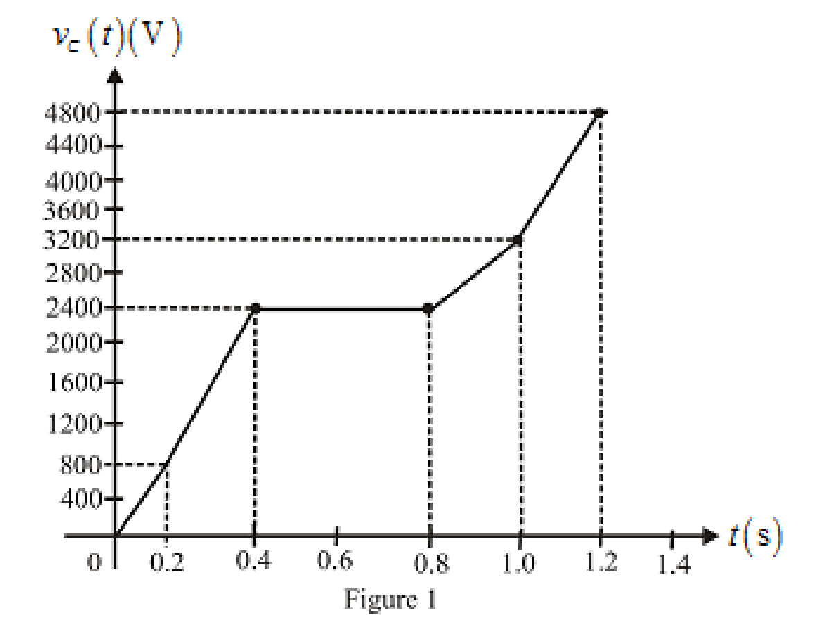
Conclusion:
Thus, the resulting voltage waveform is sketched.
(b)
Find the voltage of capacitor.
(b)
Answer to Problem 11E
The voltage of capacitor for given time duration is
Explanation of Solution
Given Data:
Value of capacitor is
Value of time duration for capacitor voltage is
Formula used:
The expression for the voltage at given point of time is,
Calculation:
Substitute
Substitute
Substitute
Conclusion:
Thus, the voltage of capacitor for given time duration is
Want to see more full solutions like this?
Chapter 7 Solutions
Engineering Circuit Analysis


- A 100µF capacitor is connected in series with a 150volt voltmeter that has a resistance of 1,000 ohms per volt. Calculate the reading of the voltmeter at the instant when t equals the time constant following the closing if the switch that impresses 120volts on the circuit.arrow_forwardFind Leq between the terminals a,b for the circuits shown below. Assuming the initial energy stored in the inductors is zero.arrow_forwardFor the circuit shown, calculate 1. the initial energy stored in the capacitors; 2. the final energy stored in the capacitors; 3. the total energy delivered to the black box; 4. the percentage of the initial energy stored that is delivered to the black box; and 5. the time, in milliseconds, it takes to deliver 7.5 mJ to the black box.arrow_forward
- The switch in the circuit shown in Fig. 7.21 has been in position a for a longtime. At t=0, the switch moves from position a to position b. The switch is amake-before-break type; that is, the connection at position b is establishedbefore the connection at position a is broken, so the inductor current iscontinuous.5. Plot both i(t) and v(t) versus t.arrow_forward3. A ceramic capacitor has an effective plate area of 5cm2 separated by 0.1mm of ceramic of relative permittivity of 100. Calculate the capacitance in microfarads. If the capacitor is given a charge of 1.5 µC what will be the potential difference (pd) between plates? & calculate the energy stored in itarrow_forward* Determine the charge stored on a 2.2 µF capacitor if the capacitor’s voltage is 5 V. *In some integrated circuits, the insulator or dielectric is silicon dioxide, which has a relative permittivity of 4. If a square capacitor measuring 10 µm on edge, has a capacitance of 100 fF, what is the separation distance between the capacitor’s plates, in µm?arrow_forward
- The current in a 20 mH inductor is known to be i=40 mA,t≤0; i=A1e−10,000t+A2e−40.000tA,t≥0. The voltage across the inductor (passive sign convention) is 28 V at t=0. 1. Find the expression for the voltage across the inductor for t>0. 2. Find the time, greater than zero, when the power at the terminals of the inductor is zero.arrow_forwardThe voltage pulse applied to the 100 mH inductor shown is 0 for t<0 and is given by the expression v(t)=20te−10t V for t>0. Also assume i=0 for t≤0. Sketch the current as a function of time.arrow_forward. A 47,000 µF capacitor, initially charged to 100 V, is discharged by a steady current of 1 mA. How long does it take to discharge the capacitor to 0 V? a. Is this discharge time long or slow? Explainarrow_forward
- Two coils of inductance 6 H and 8 H are connected in parallel. If their coefficient of coupling is 0.435, calculate the equivalent inductance of the combination if (a) the mutual inductance assists the self-inductance, and (ii) the mutual inductance opposes the self-inductance.arrow_forwardCalculate the energy stored in a parallel-plate capacitor which consists of two metal plates, each 60cm2 separated by a dielectric 1.5mm thick and of relative permittivity 3.5 if a p.d. of 1000 v is applied across it.arrow_forwardThe distance between the plates of a capacitor, which consists of a square plate with a side length of 3 cm, is 2mm. The dielectric coefficient of the insulator is 2. If the maximum electric field that the air can withstand is 2.10 ⁶ V / m, find the maximum load the capacitor can carry.arrow_forward
 Introductory Circuit Analysis (13th Edition)Electrical EngineeringISBN:9780133923605Author:Robert L. BoylestadPublisher:PEARSON
 Delmar's Standard Textbook Of ElectricityElectrical EngineeringISBN:9781337900348Author:Stephen L. HermanPublisher:Cengage Learning
 Programmable Logic ControllersElectrical EngineeringISBN:9780073373843Author:Frank D. PetruzellaPublisher:McGraw-Hill Education
 Fundamentals of Electric CircuitsElectrical EngineeringISBN:9780078028229Author:Charles K Alexander, Matthew SadikuPublisher:McGraw-Hill Education
 Electric Circuits. (11th Edition)Electrical EngineeringISBN:9780134746968Author:James W. Nilsson, Susan RiedelPublisher:PEARSON
 Engineering ElectromagneticsElectrical EngineeringISBN:9780078028151Author:Hayt, William H. (william Hart), Jr, BUCK, John A.Publisher:Mcgraw-hill Education,