
Concept explainers
Videos
(a)
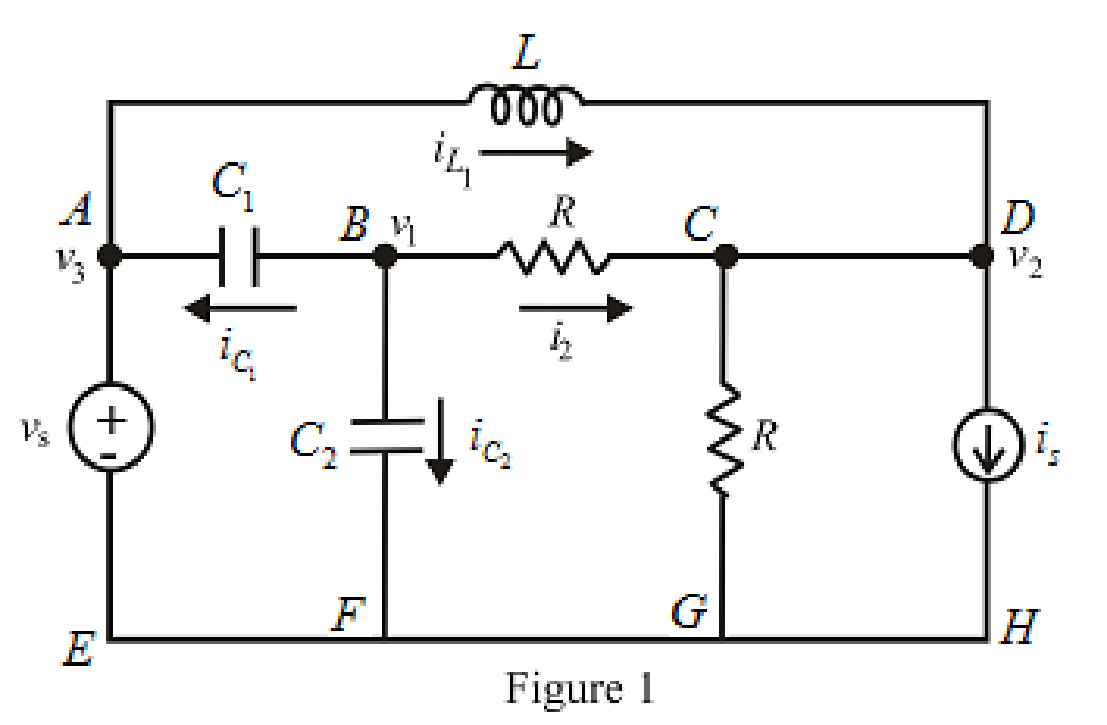
Write the nodal equation of the circuit.
(a)
Answer to Problem 45E
The nodal equation of the circuit at node voltage
Explanation of Solution
Calculation:
The redrawn circuit is shown in Figure 1.
Here,
The expression for the current across the inductor is,
Here,
The expression for the current across capacitor is,
Here,
The expression for the nodal analysis at node
Rearrange equation (3),
The voltage at node voltage
Substitute
The expression for the nodal analysis at node voltage
The node voltage across resistance
Rearrange equation (7),
Conclusion:
Thus, the nodal equation of the circuit at node voltage
(b)
Write the mesh equation of the circuit.
(b)
Answer to Problem 45E
The mesh equation of the circuit in loop
Explanation of Solution
Calculation:
The redrawn circuit is shown in Figure 2 as follows,
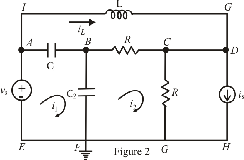
Refer to the Figure 2,
The voltage at node voltage
The expression for mesh equation in loop
Here,
Substitute
The expression for mesh equation in loop
Substitute
The expression for mesh equation in loop
Conclusion:
Thus, the mesh equation of the circuit in loop
Want to see more full solutions like this?
Chapter 7 Solutions
Engineering Circuit Analysis


- In particular, a system may or may not be(1) Memoryless(2) Time invariant(3) Linear(4) Causal(S) StableDetermine which of these properties hold and which do not hold for the following continuous-time system. Justify your answers.arrow_forward7. 7.27 In the circuit the voltage and current expressions are v=48e−25t V, t≥0;i=12e−25t mA, t≥0+.Find1. a) R.2. b) C.3. c) τ (in milliseconds).4. d) the initial energy stored in the capacitor.5. e) the amount of energy that has been dissipated by the resistor 60ms after the voltage begins to decay.arrow_forwardThe switch in the circuit shown in Fig. 7.21 has been in position a for a longtime. At t=0, the switch moves from position a to position b. The switch is amake-before-break type; that is, the connection at position b is establishedbefore the connection at position a is broken, so the inductor current iscontinuous.5. Plot both i(t) and v(t) versus t.arrow_forward
- 18. Two coils of inductances 4 H and 6 H are connected in parallel. If their mutual inductance is 3 H. Calculate the equivalent inductance of the combination if mutual inductance assists and if mutual inductance opposes the self-inductance respectively.arrow_forward1. Find the outer radius of a coaxial cable having a characteristic impedance of 12 and a dielectric constant of 0.06. The outer inner radius of this cable is 4 cm. 2. How much is the inductance of a coil of an instrument that induces 1000 V when its current changes at the rate of 50 mA in 2 µsarrow_forwardsolve for the computed values only, please show complete solution.arrow_forward
- consider the translational mechanical network system a 1lb force f(t), si applied at t=0 if fv=1 find K and M such response is characterized by 4 sec settling time and 1 sec peak time also what is the resulting %OSarrow_forward7.4 The switch in the circuit shown has been closed for a long timebefore being opened at t=0.2. b) What percentage of the initial energy stored in the circuit hasbeen dissipated after the switch has been open for 60 ms?arrow_forwardFor the circuit shown, calculate 1. the initial energy stored in the capacitors; 2. the final energy stored in the capacitors; 3. the total energy delivered to the black box; 4. the percentage of the initial energy stored that is delivered to the black box; and 5. the time, in milliseconds, it takes to deliver 7.5 mJ to the black box.arrow_forward
- An iron ring 20 cm mean radius is made of square of iron of 3 cm × 3 cm cross-section and is uniformly wound with 350 turns of wire of 2 mm2 cross-section. Calculate the value of the self-inductance of the coil. Assume μr = 800.arrow_forward1. Theoretically calculate the voltage across the capacitor in the circuit of Figure 1 when t = 0 s, 5 s, 10 s, 20 s, 30 s, 40 s, and 60 s, assuming that the circuit is under DC conditions when t < 0 s and the switch is opened at t = 0 s. 2. Compare the calculated voltage at t = 20 s with the experimentally measured ∆?.arrow_forward6 A capacitor is constructed with parallel metal plates, If the plate separation is 2 mm and the capacitance is given to 1 nano Farads, determine the area of the parallel plates of the device. Select one: a. 0.12 square meters b. 0.23 square meters c. 0.27 square meters d. 0.20 square metersarrow_forward
 Introductory Circuit Analysis (13th Edition)Electrical EngineeringISBN:9780133923605Author:Robert L. BoylestadPublisher:PEARSON
 Delmar's Standard Textbook Of ElectricityElectrical EngineeringISBN:9781337900348Author:Stephen L. HermanPublisher:Cengage Learning
 Programmable Logic ControllersElectrical EngineeringISBN:9780073373843Author:Frank D. PetruzellaPublisher:McGraw-Hill Education
 Fundamentals of Electric CircuitsElectrical EngineeringISBN:9780078028229Author:Charles K Alexander, Matthew SadikuPublisher:McGraw-Hill Education
 Electric Circuits. (11th Edition)Electrical EngineeringISBN:9780134746968Author:James W. Nilsson, Susan RiedelPublisher:PEARSON
 Engineering ElectromagneticsElectrical EngineeringISBN:9780078028151Author:Hayt, William H. (william Hart), Jr, BUCK, John A.Publisher:Mcgraw-hill Education,